
From Upcycled Parts.
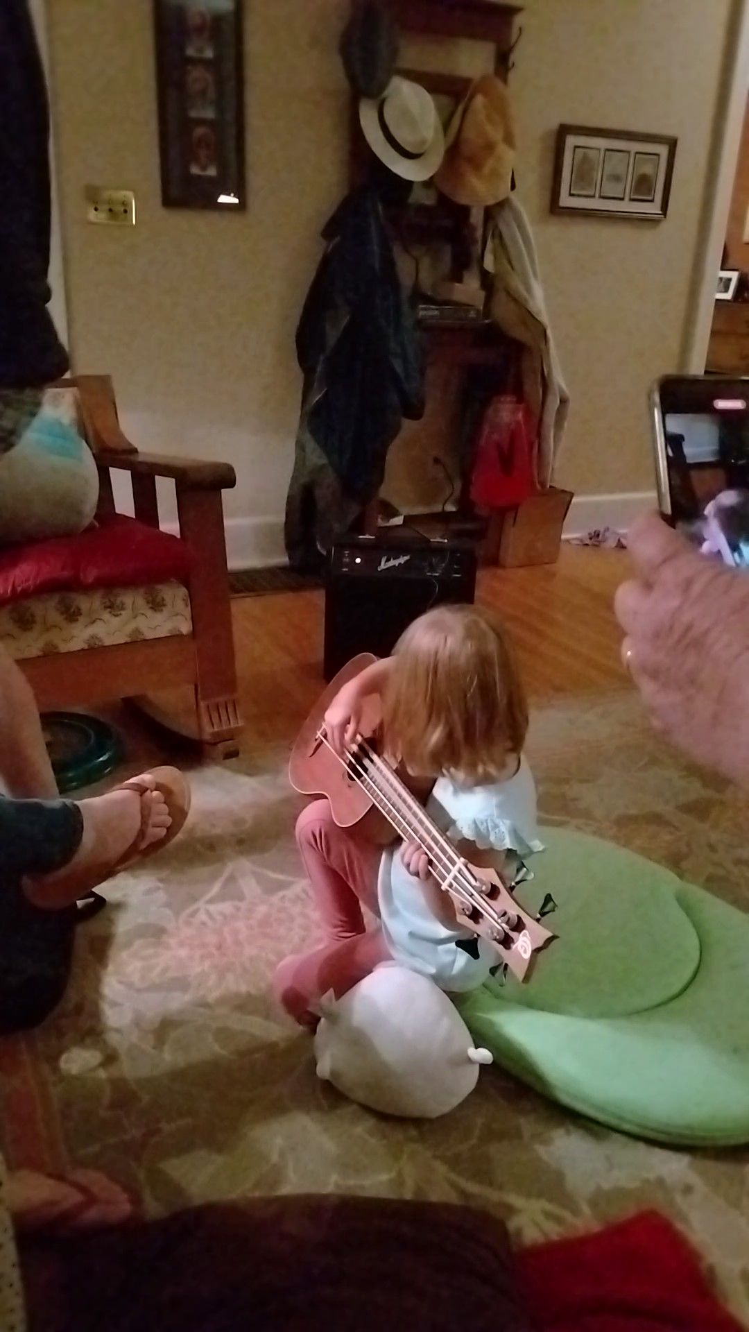
Two awesome guys gave the grandkids a fine bass ukulele for Christmas this year (Thanks Mike and B.J.!). It has a built-in tuner and pickup and is best enjoyed with an amplifier, so I thought I would make a practice amplifier for it using parts on hand. This is a story of that journey.
I had an amplifier board salvaged from an old flat screen television that I had always wanted to use for something, so I decided to build it around that. It had several wires coming off it to figure out how to hook up. I used the negative terminals of on-board capacitors to establish the negative side of the power supply input and assumed the other wires on the same connector were the positive side. This left the inputs and outputs to sort out. I found the datasheet for the amplifier I.C. that the board used online and was able to dope out the remaining connections.
The I.C. is an NXP TDA8932B Class-D audio amplifier, which is very efficient and runs cool without any heatsink other that the circuit board itself. It was configured for stereo, but using the datasheet’s reference designs, I was able to modify the board to use it in Bridge Tied Load (BTL) mono configuration for a maximum of 30 watts of output power. This require removing some components and adding some surface mount resistors and wires. I used test points on the bottom of the board as a location to add these modifications, so you don’t notice much change from the top side.
There was no provision for volume control, so I set up a voltage divider using a potentiometer with an audio taper of an arbitrary value on the input. I wired the volume control with some vintage shielded cable salvaged from a pro audio console.
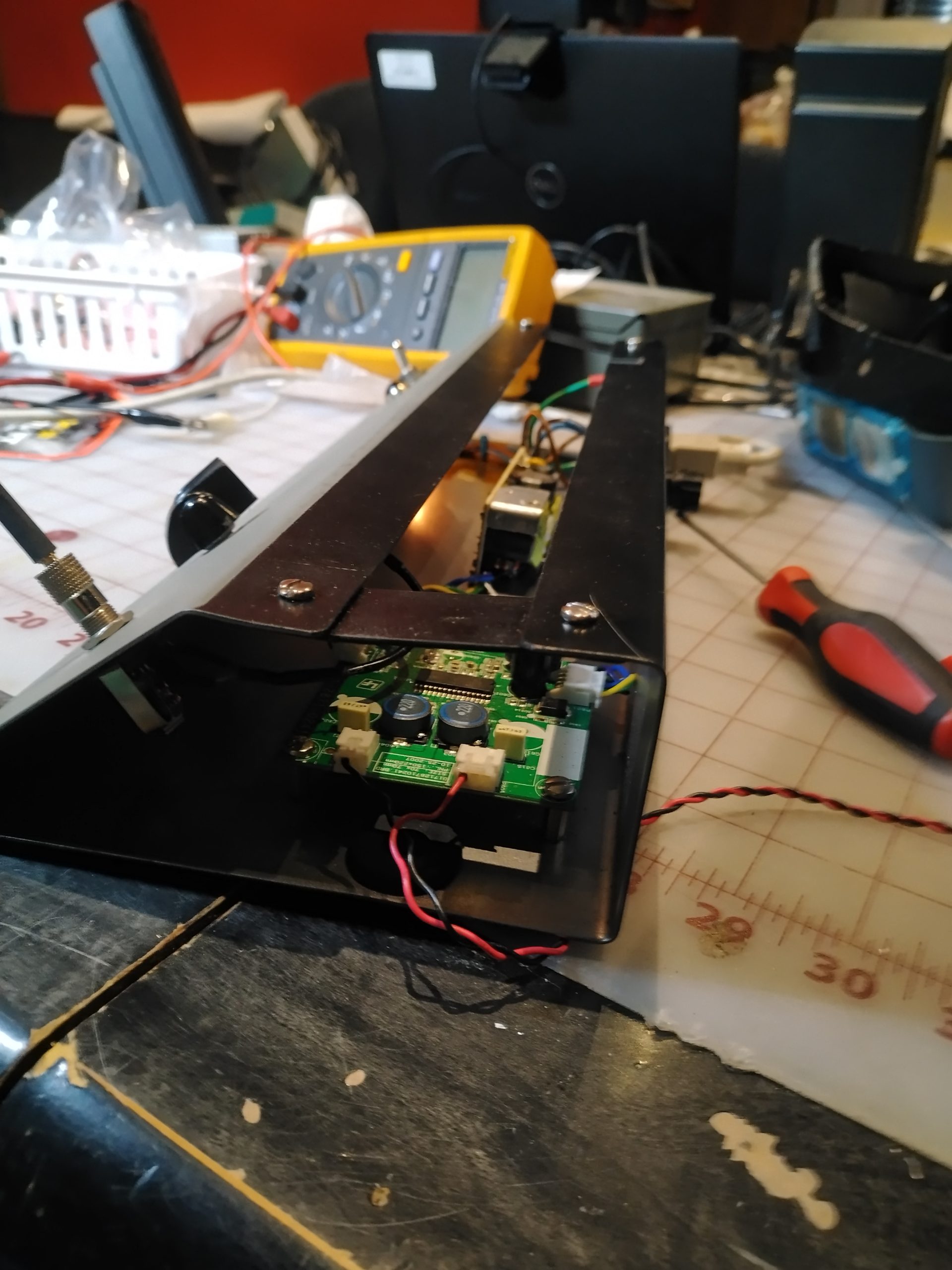
That was phase one of the project. I bench tested this out to make sure everything worked before proceeding. This photo shows testing it out before the BTL modifications. The two large electrolytic capacitors have since been removed.

The power supply was selected from the hoard pile of plug-in wall transformers, aka wall-warts. Luckily, the amplifier board had configured the TDA8932B for asymmetrical supply and did not seem to have any additional on-board voltage regulators, so I just had to pick out a supply that fell between the TDA8932B’s parameters of 10 – 22 volts with sufficient current.
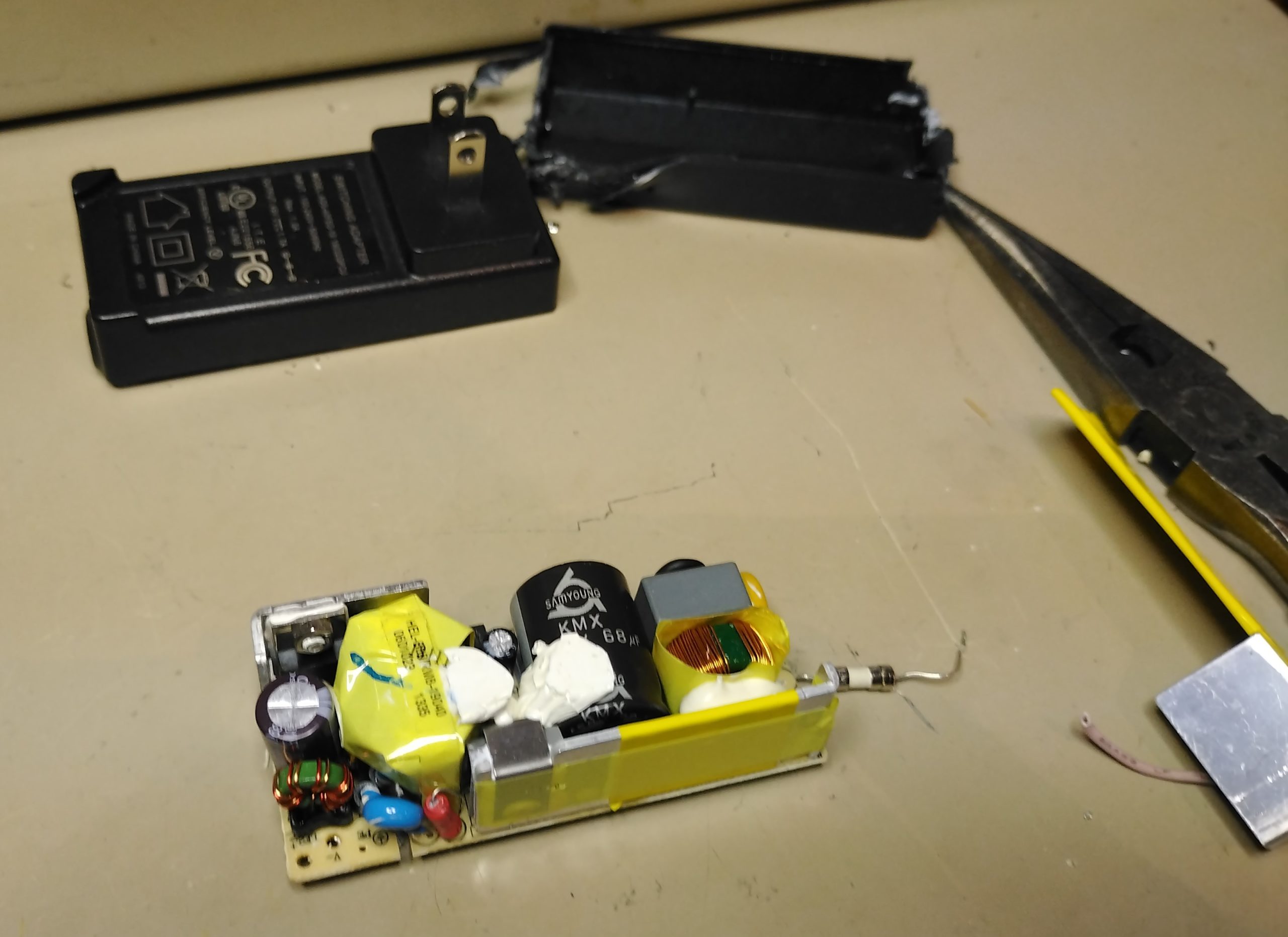
I picked out a switched-mode power supply that was probably from and old printer. Switched-mode power supplies are also very efficient and run cooler than their linear counterparts. This one was sealed inside a closely-fitting plastic enclosure in its original use, so it had to run cool. I extracted the power supply from its case and replaced the soldered-in fuse with a piece of buss wire since I was going to incorporate an external fuse holder.
Both class-D amplifiers and switched-mode power supplies are looked down upon by audio purists, but this is not an audiophile project. It is for a bass ukulele. The reason for their derision is the possibility of noise from the high frequencies these two modern technologies utilize. This is somewhat evident in the television manufacturer’s use of a ferrite choke on the speaker leads of this amplifier. You don’t normally see that. The datasheet for the TDA8932B claims a total harmonic distortion-plus-noise figure of 0.007% at 1kHz and 0.05% at 6kHz and an output noise voltage of 100 µV, if these figures mean anything to you. With no input and the volume turned all the way up, I cannot hear anything coming from the speaker.
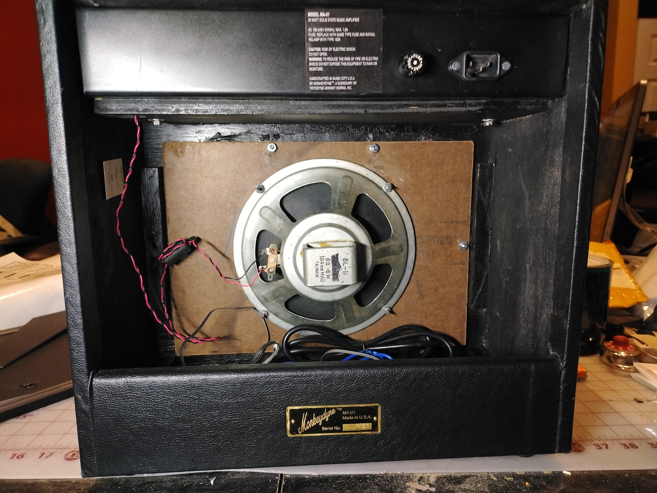
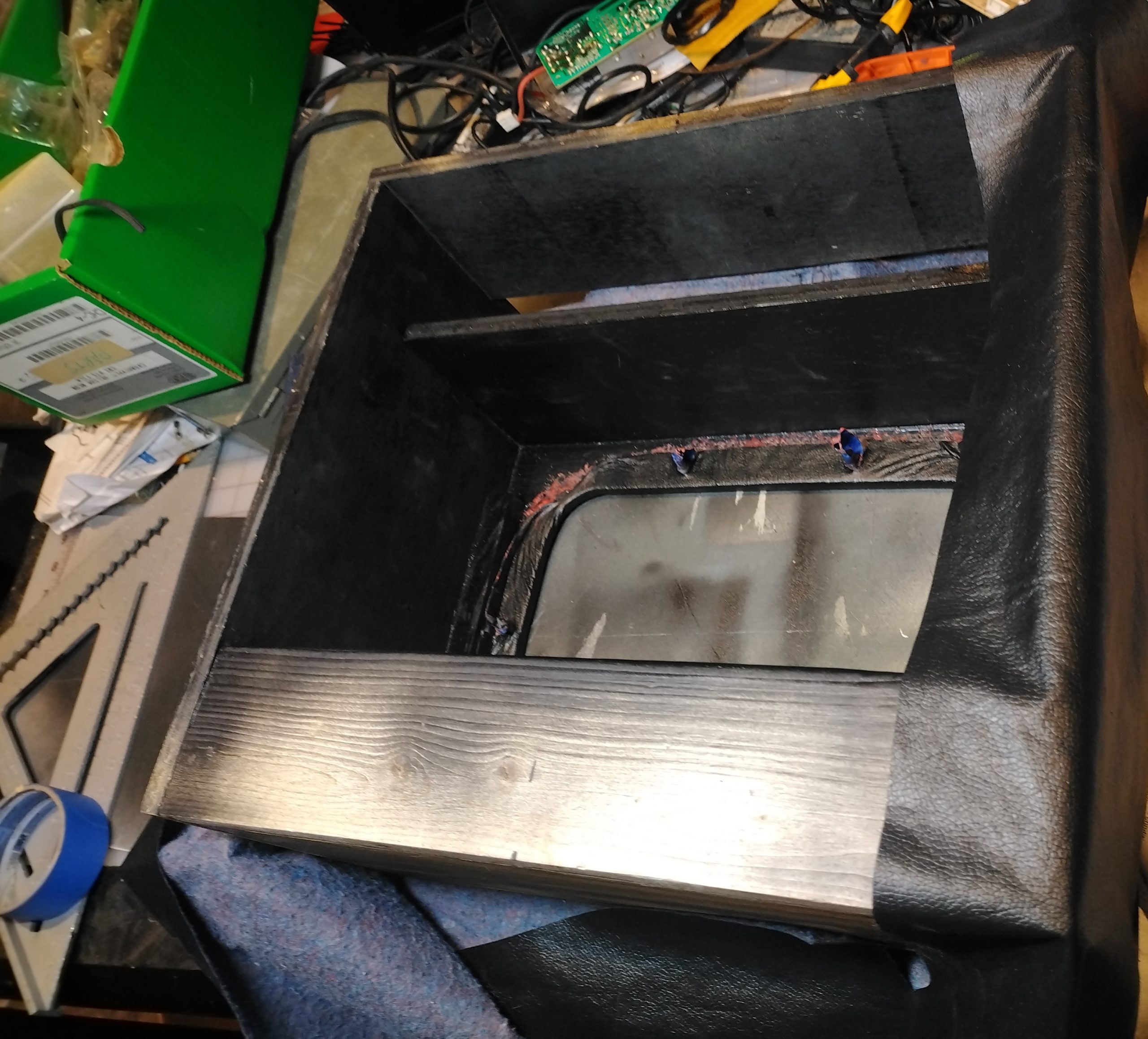
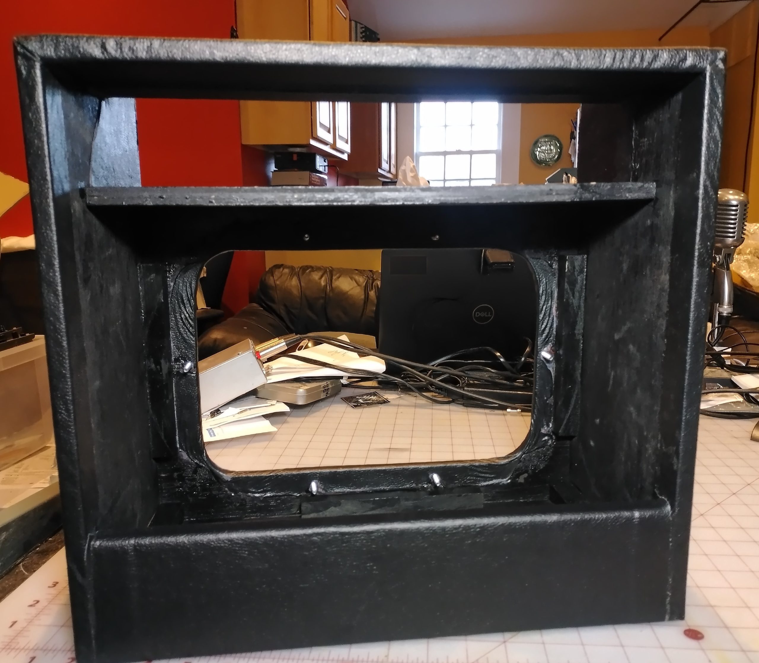
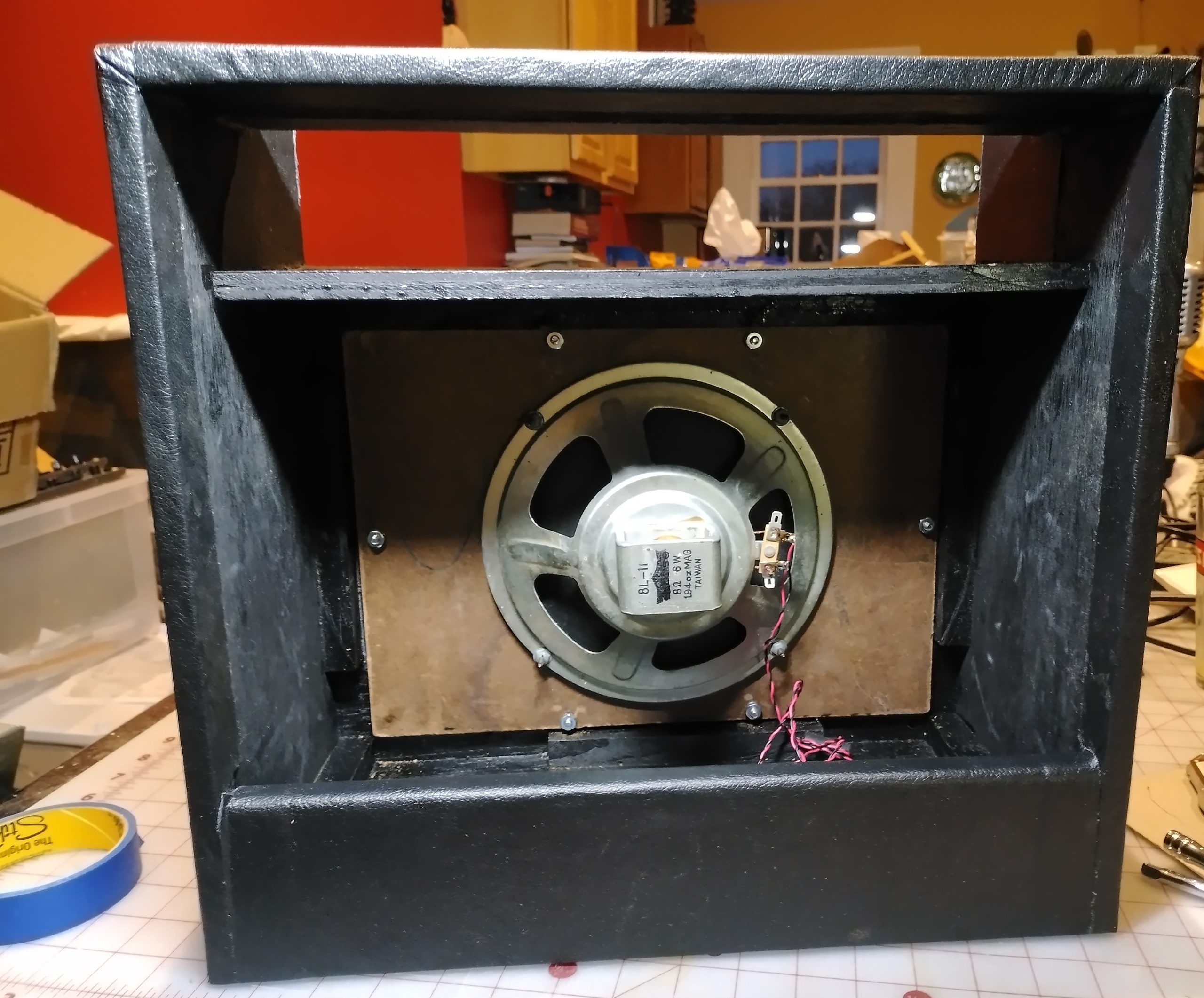
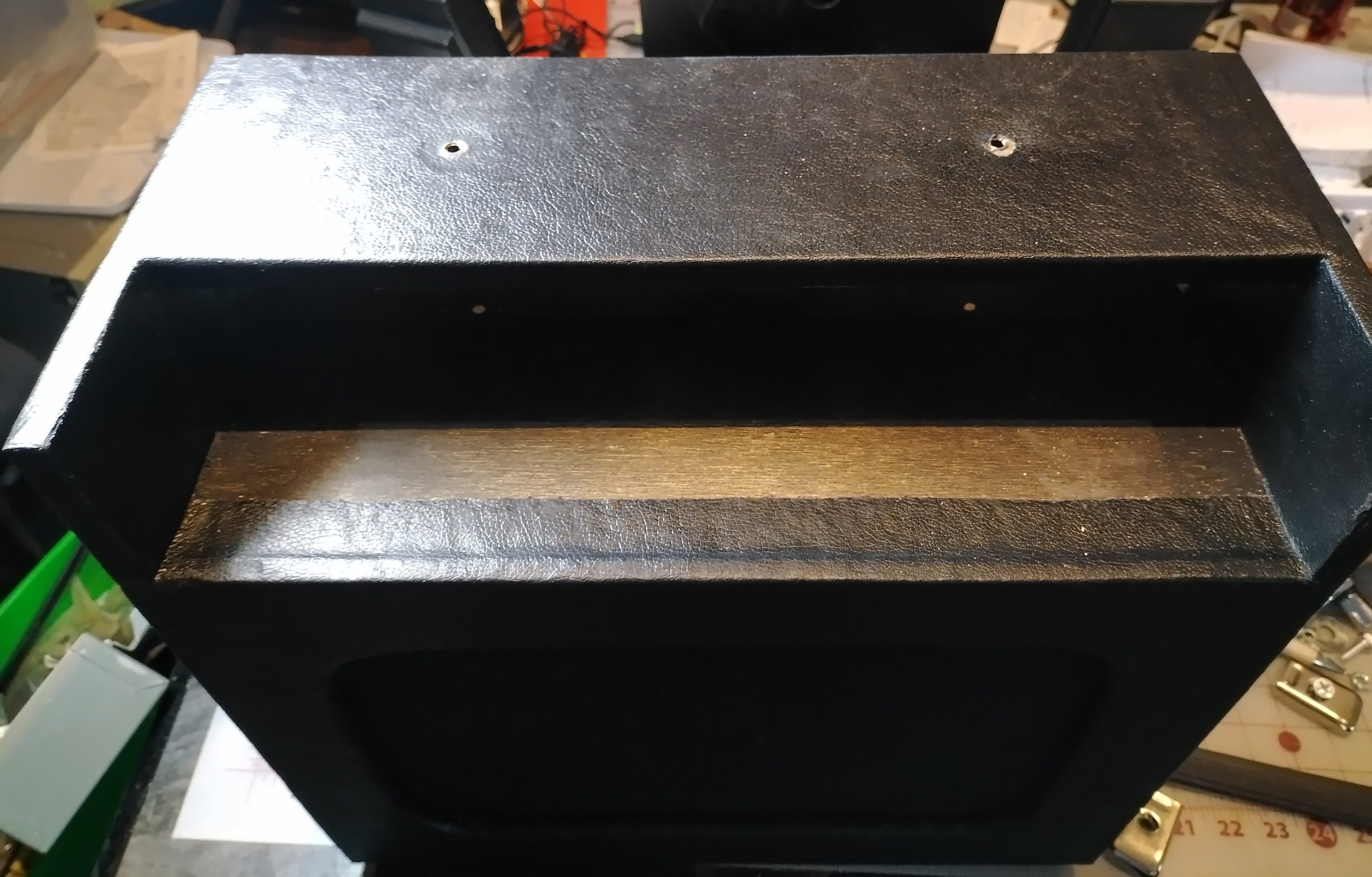
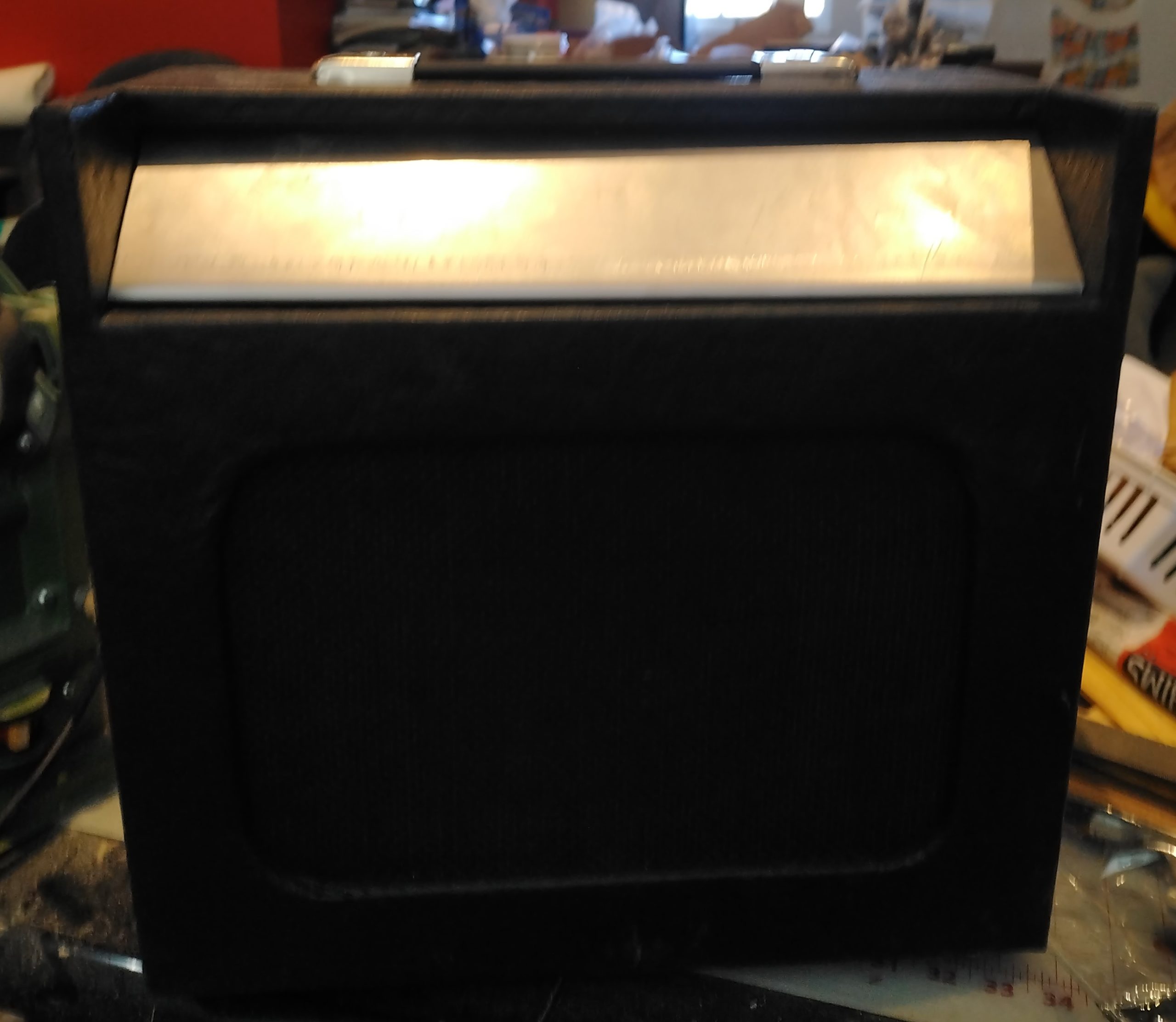
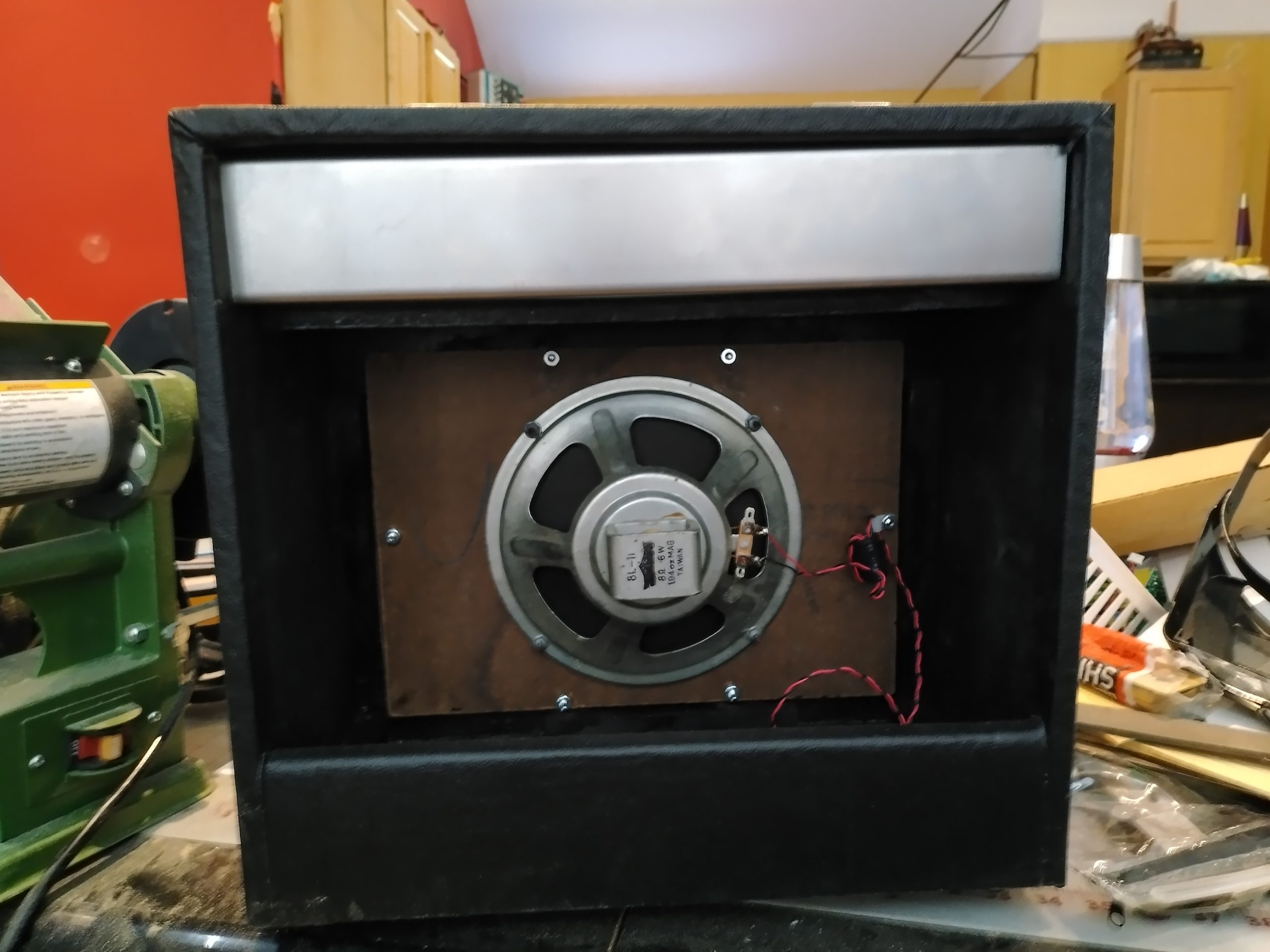
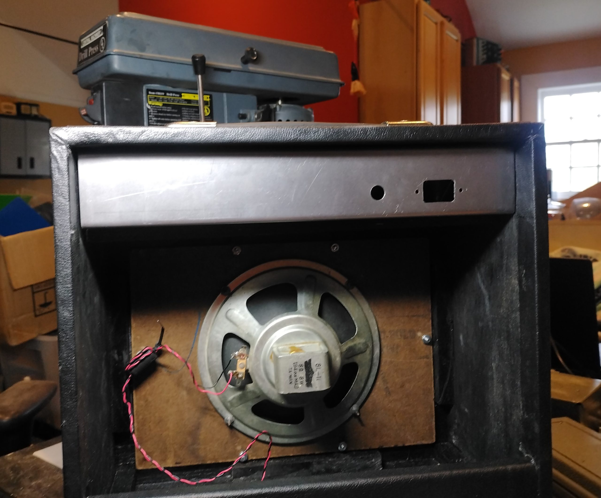
Phase two of the project was to build the cabinet. When looking for a speaker, I found in the basement a 1970’s flood damaged floor speaker salvaged from the local Radio Shack when it closed. There was no cabinet, just the hardboard front baffle, grill cloth and the 8-ohm speaker itself. The cabinet was built around this.
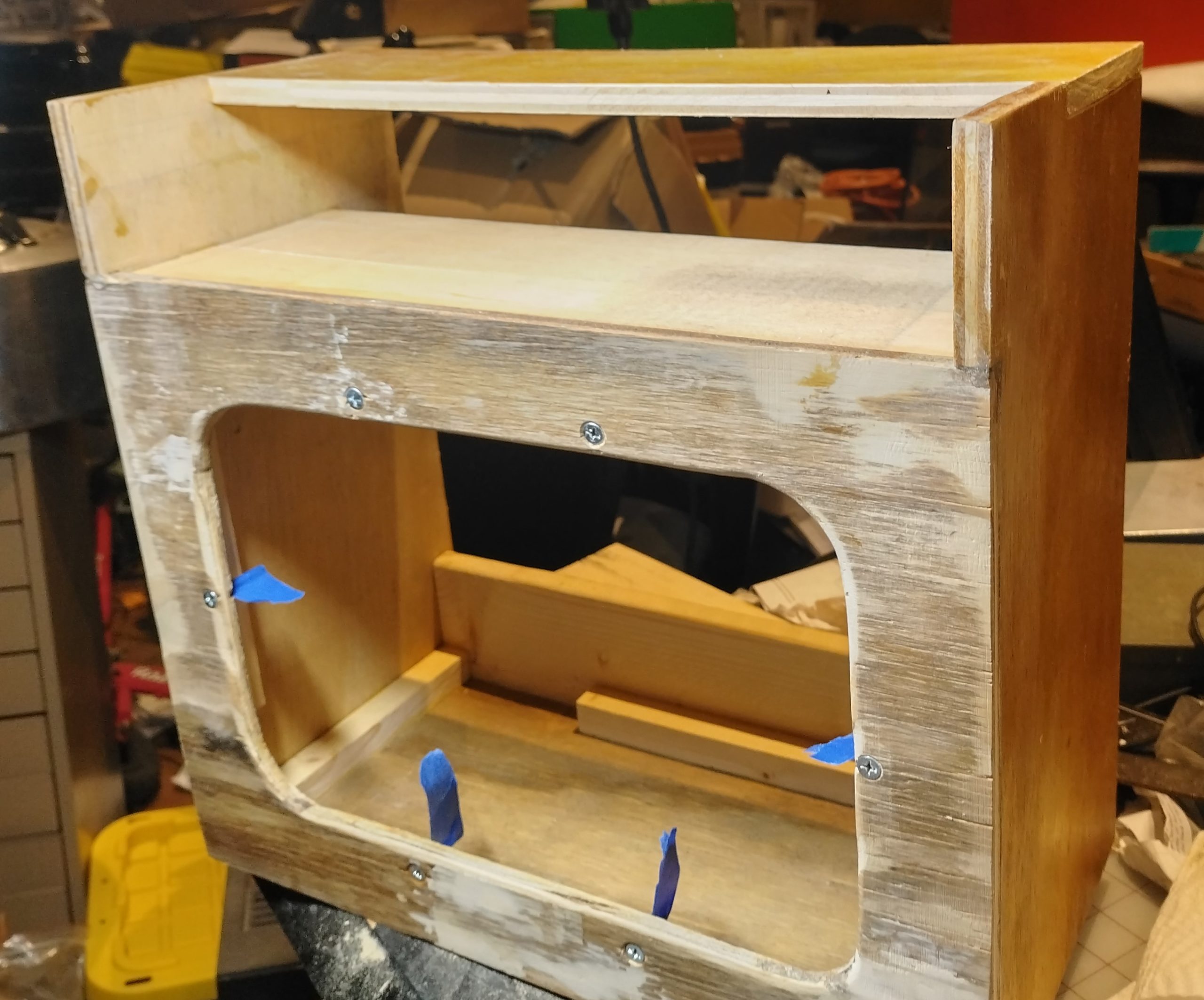
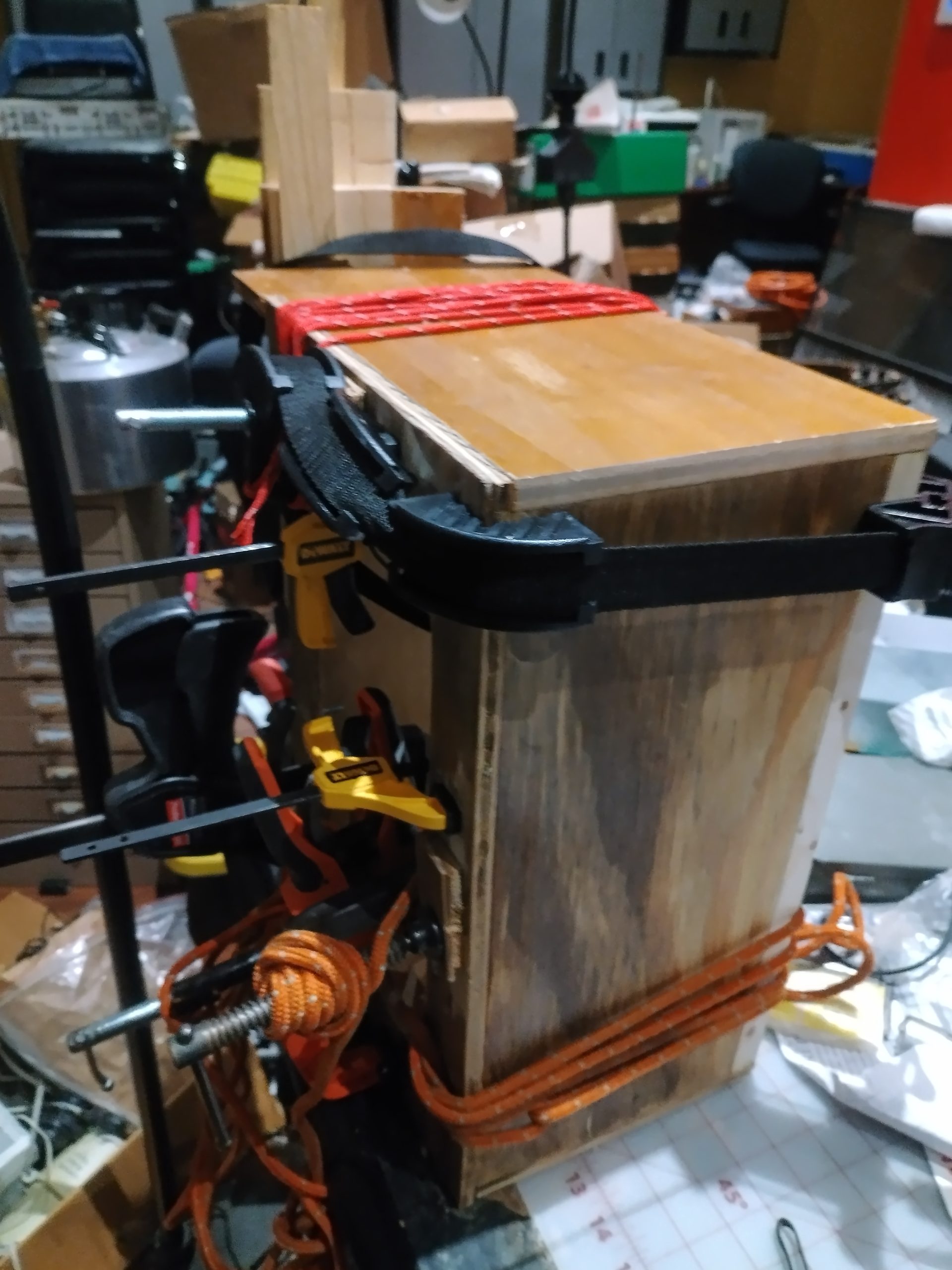
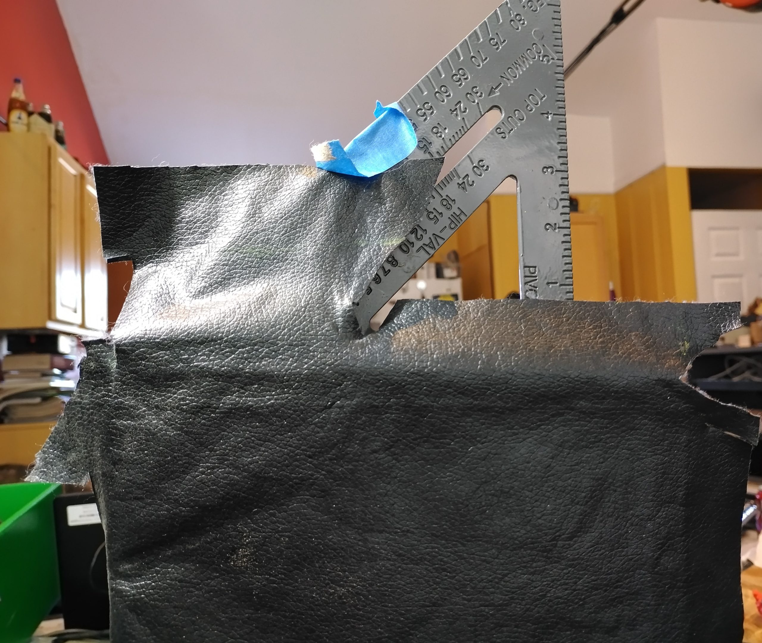
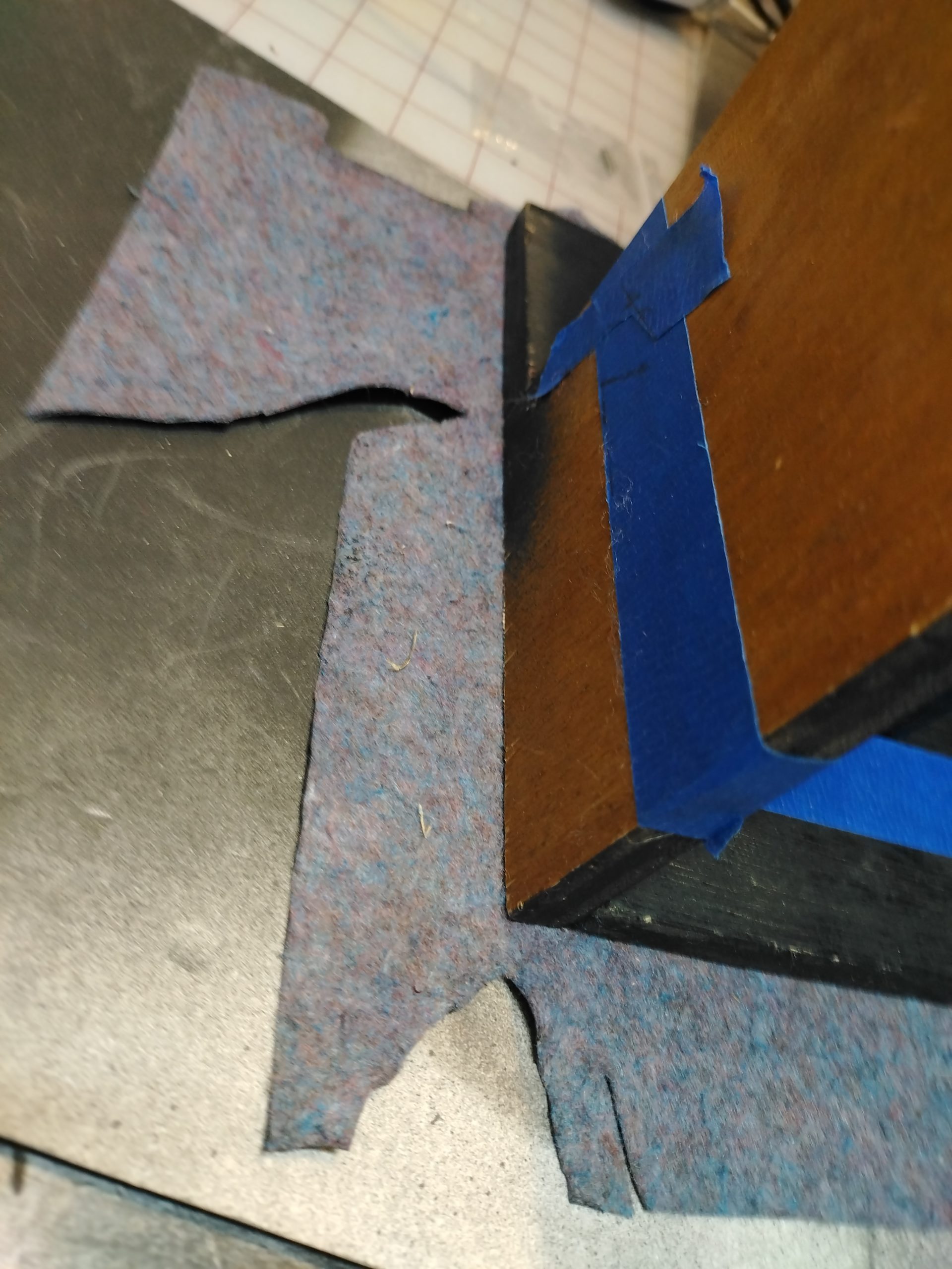
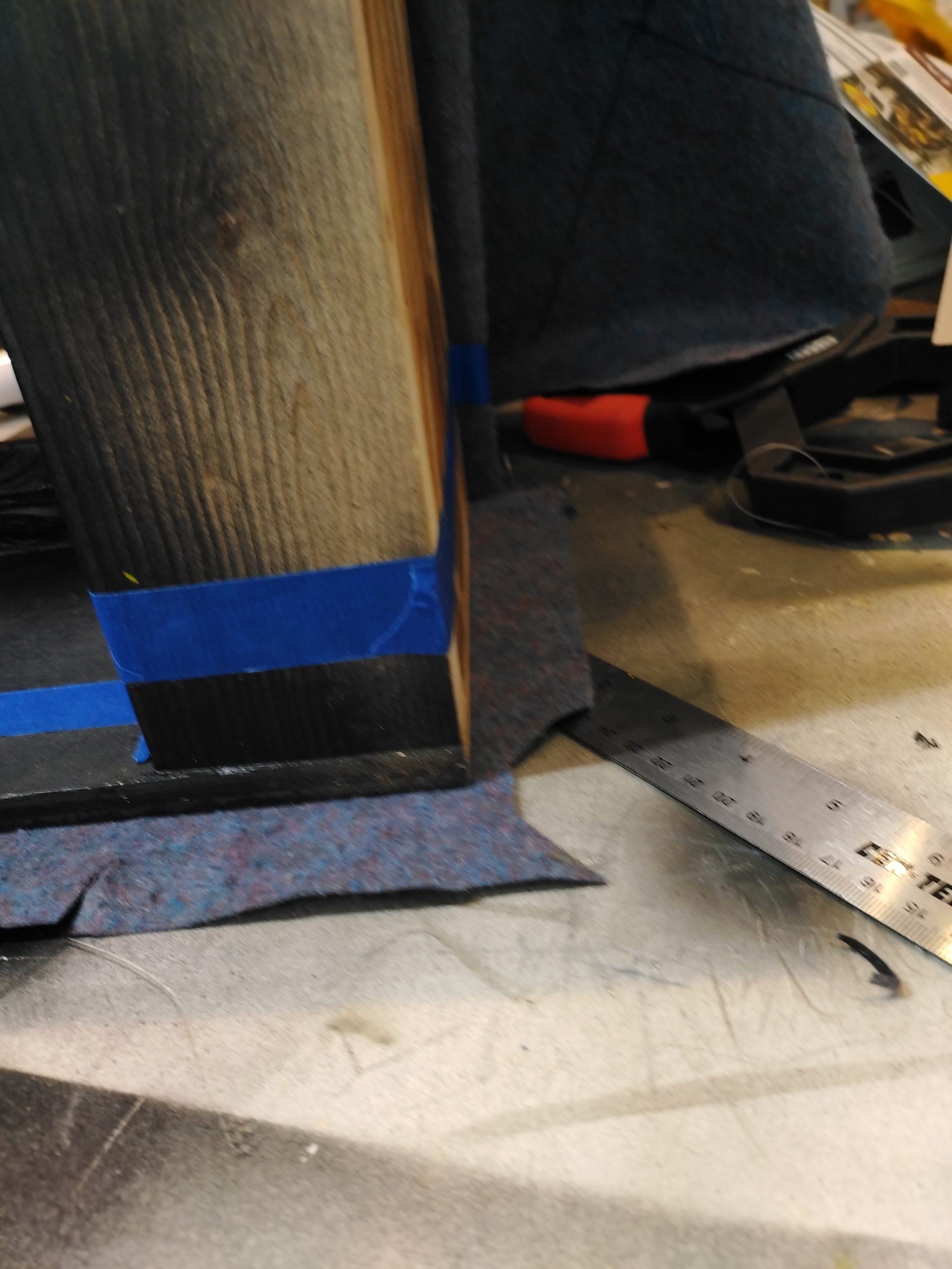
I had some scrap plywood on hand. In case a child decided to sit on the thing, I made the sides and top from thicker plywood. The sides support the top and extend all the way to the bottom. This increased complexity, because what could have been two simple rectangles now have eight sides because of how they are notched. In addition to being notched for the top, the sides are also notched for the front to avoid having any seams on the front. Glue blocks and the lower back were made from solid wood that came from my futon.
I cut down the plywood using a table saw. This should be done using a sled, or a panel saw, or a track saw. Not having any of those made for unpleasant work. The rest of the pieces were cut using a powered miter saw, a scroll saw, and a jig saw. Radii were cut using hole saws. I beveled and smoothed the speaker opening with a hand rasp and a sander.
I had a half-hearted self-imposed constraint of trying to build this without purchasing anything. I didn’t want to order and wait on special speaker stud bolts, so I screwed and CA glued regular flat head machine screws into tight fitting beveled holes to secure the front baffle to the case. Everything was glued up using Titebond II wood glue.

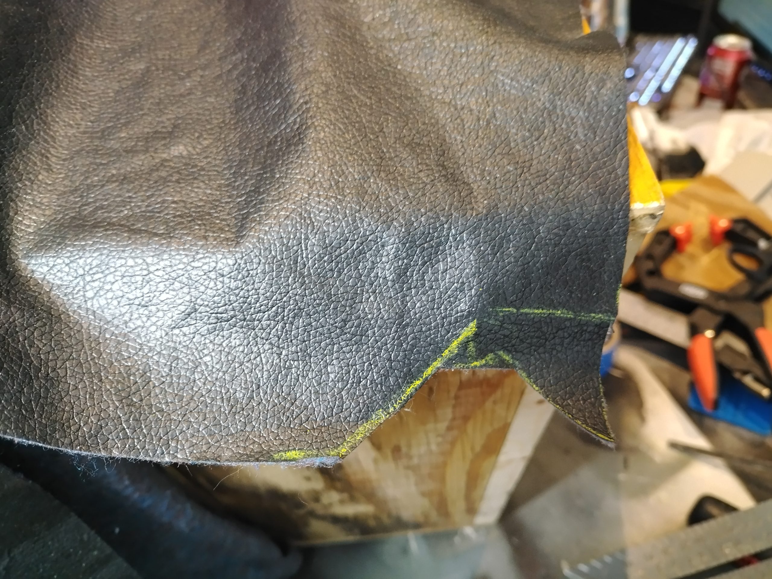
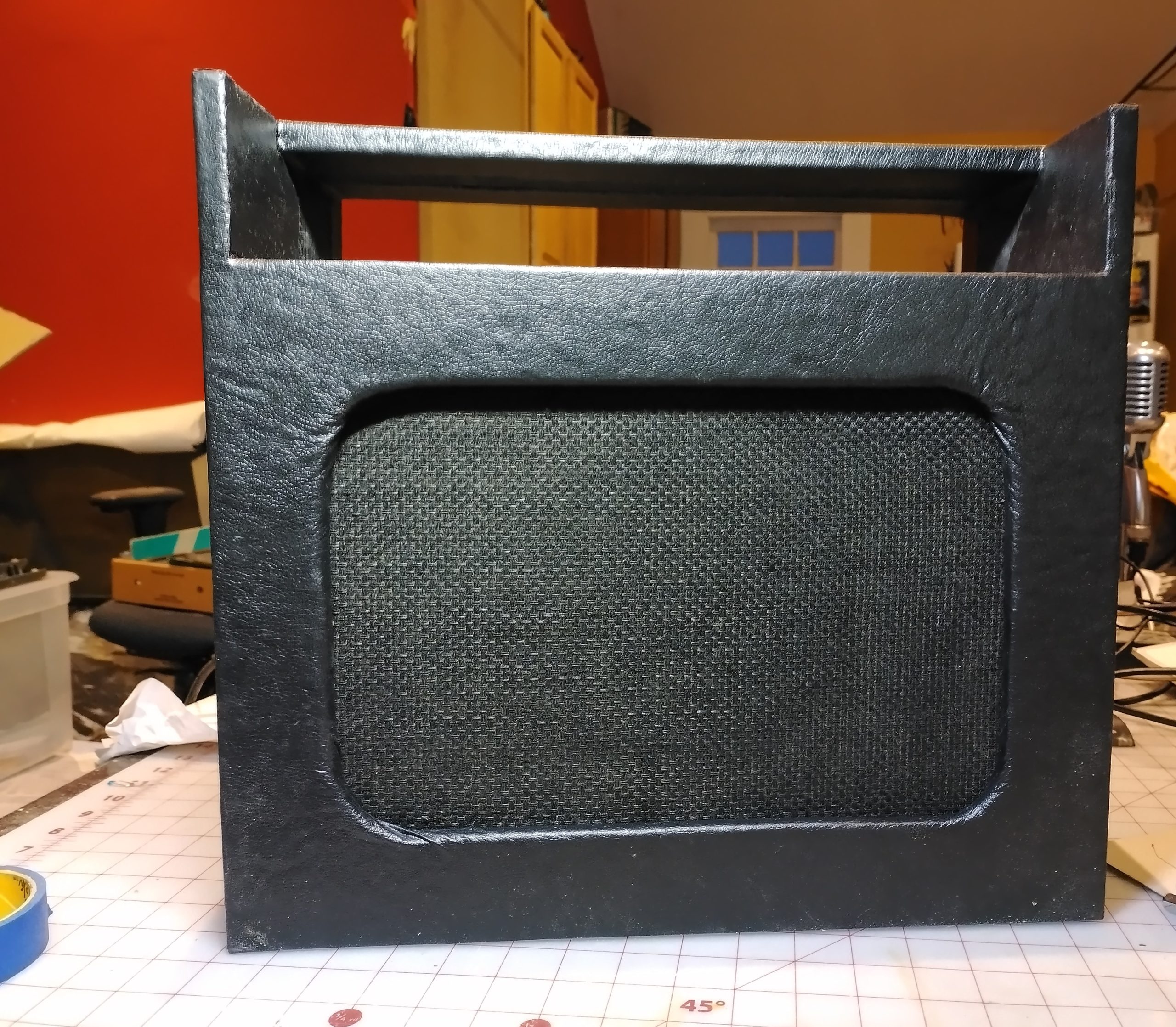
Next, on to the covering. I had some fabric I had purchased to make a camera bellows for the wet plate photography project. This is not nearly as rugged as the real thing, but it looks the part. I have never covered anything this way before, and knowing I only had one shot at this, I proceeded very cautiously. I only had enough fabric for one attempt and there would no easy way to remove it from the cabinet once glued on. I laid out a pattern that would cover five out of nine of the largest faces with just one continuous piece. I did only one side a day, masking everything off, applying spray contact adhesive, removing the masking, smoothing everything down, then doing this all over again the next day for several days. I had some spray adhesive that came from Unclaimed Freight years ago. It came out pink. You let it dry for a couple of minutes until it turns rose colored then apply the fabric to the surface. It is nearly immediately permanently attached and cannot be moved or repositioned. I used the whole can and then purchased a can of 3M 90. I used a butane torch lighter to remove nap and to fuse edges. When they remodeled the Kroger’s, they had these lighters on clearance for $4.
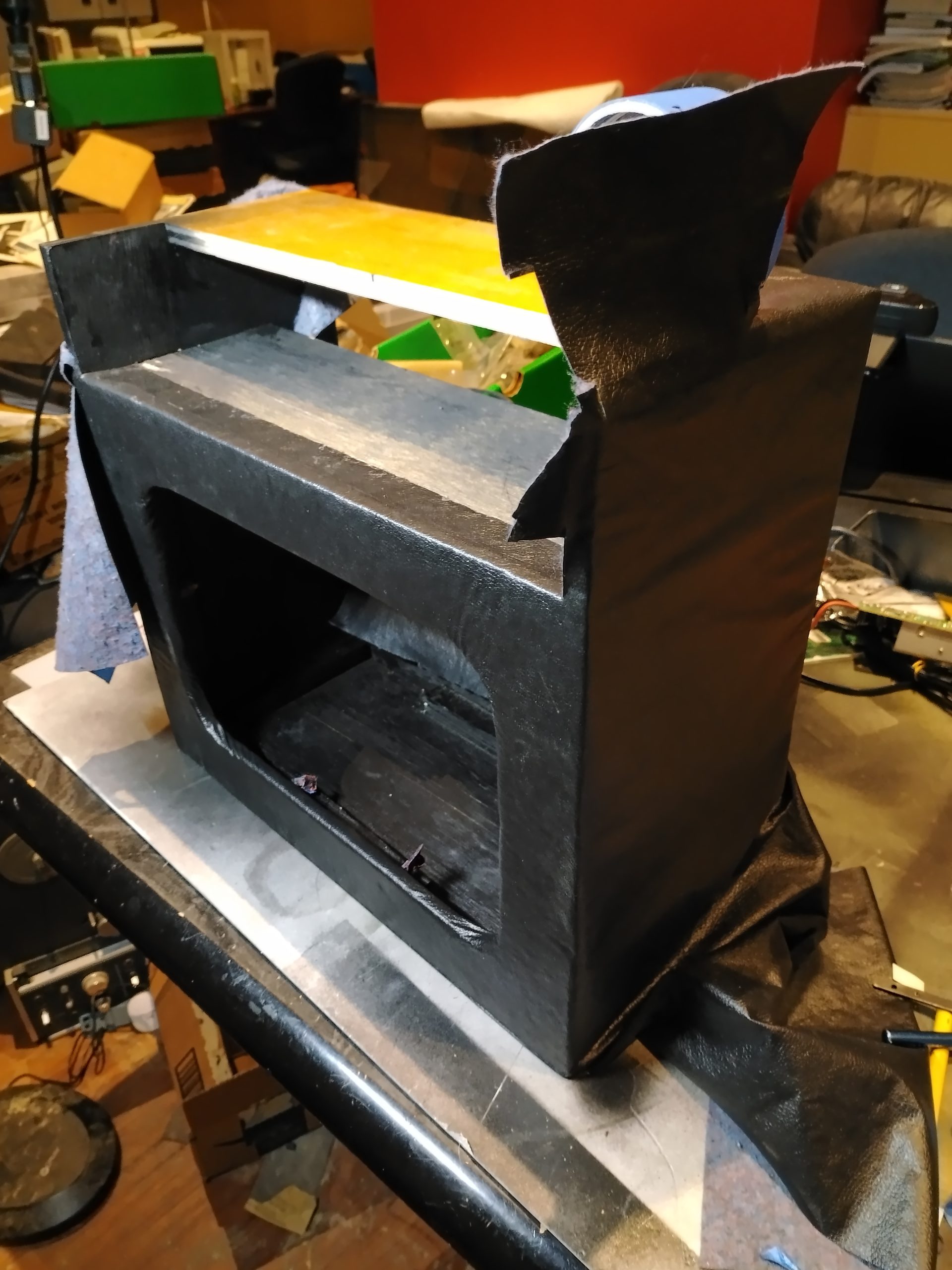
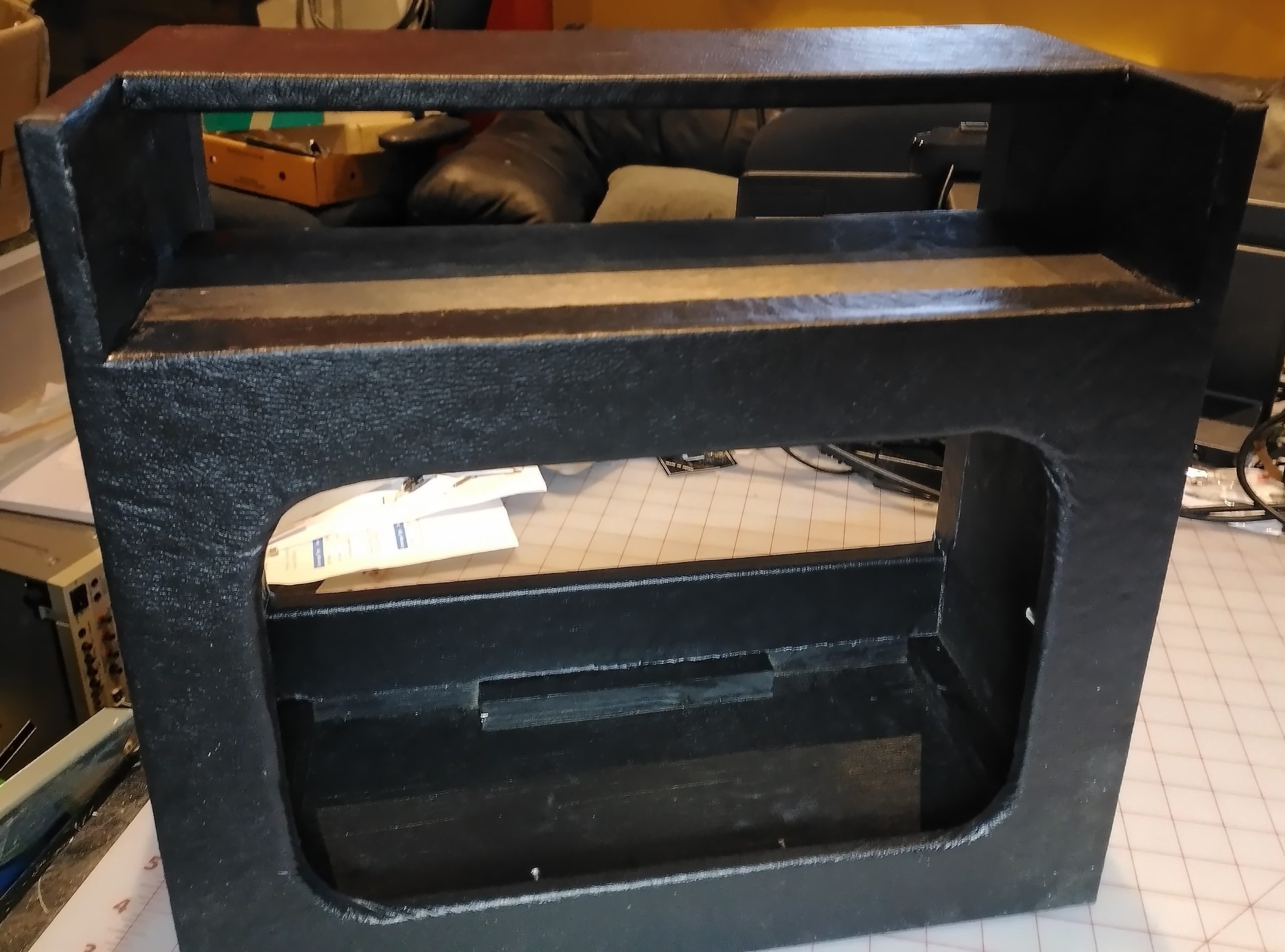
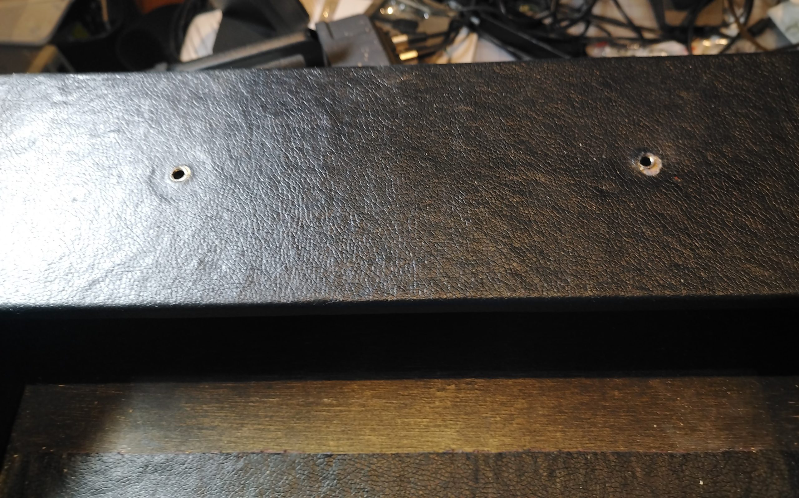
The finished covered back.
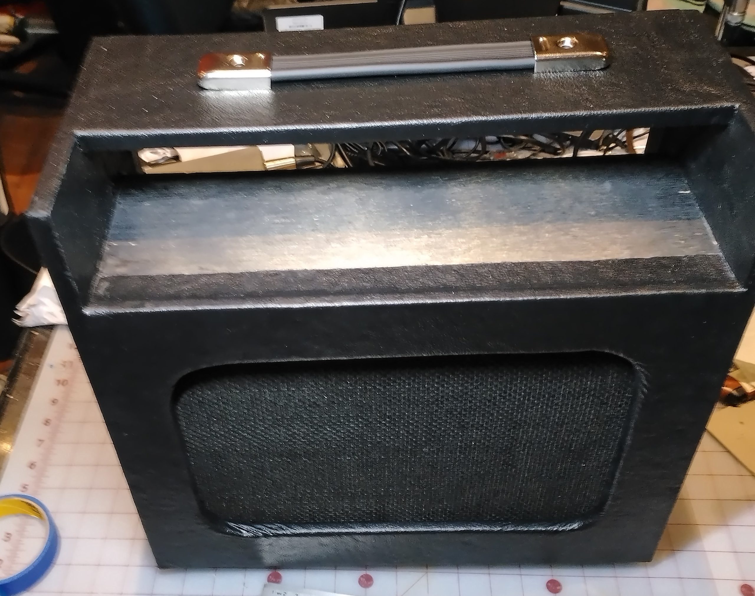
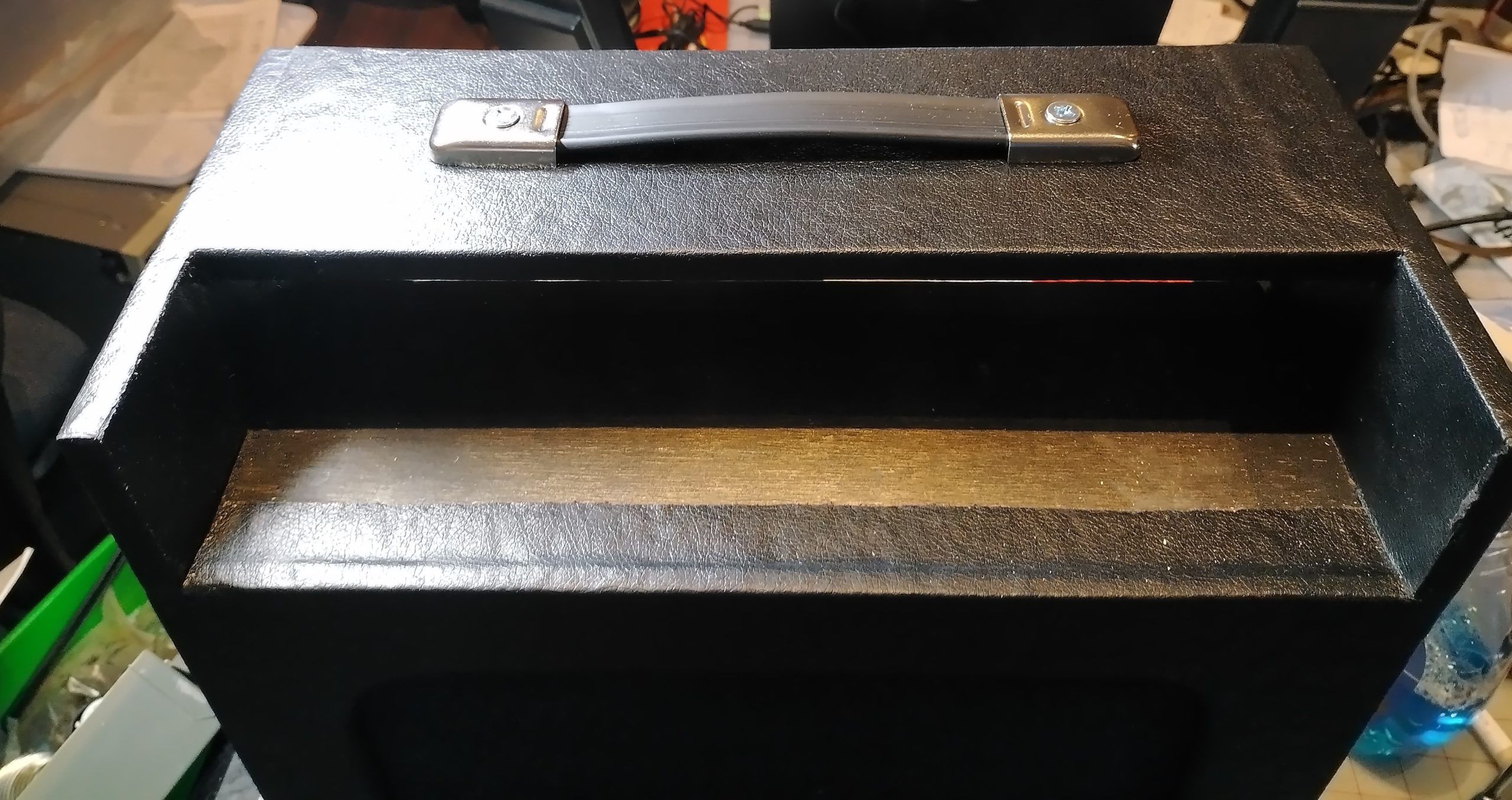
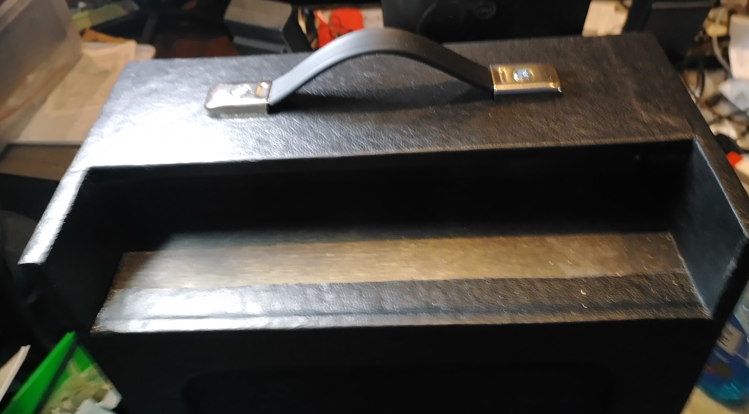
I purchased this handle and some rubber feet from TubesandMore.com. I had hoped to come across something like an old record player or luggage handle but never did. It pains me just a little that the screws are galvanized and not chromed like the mounts. The important part is that this project is complete.
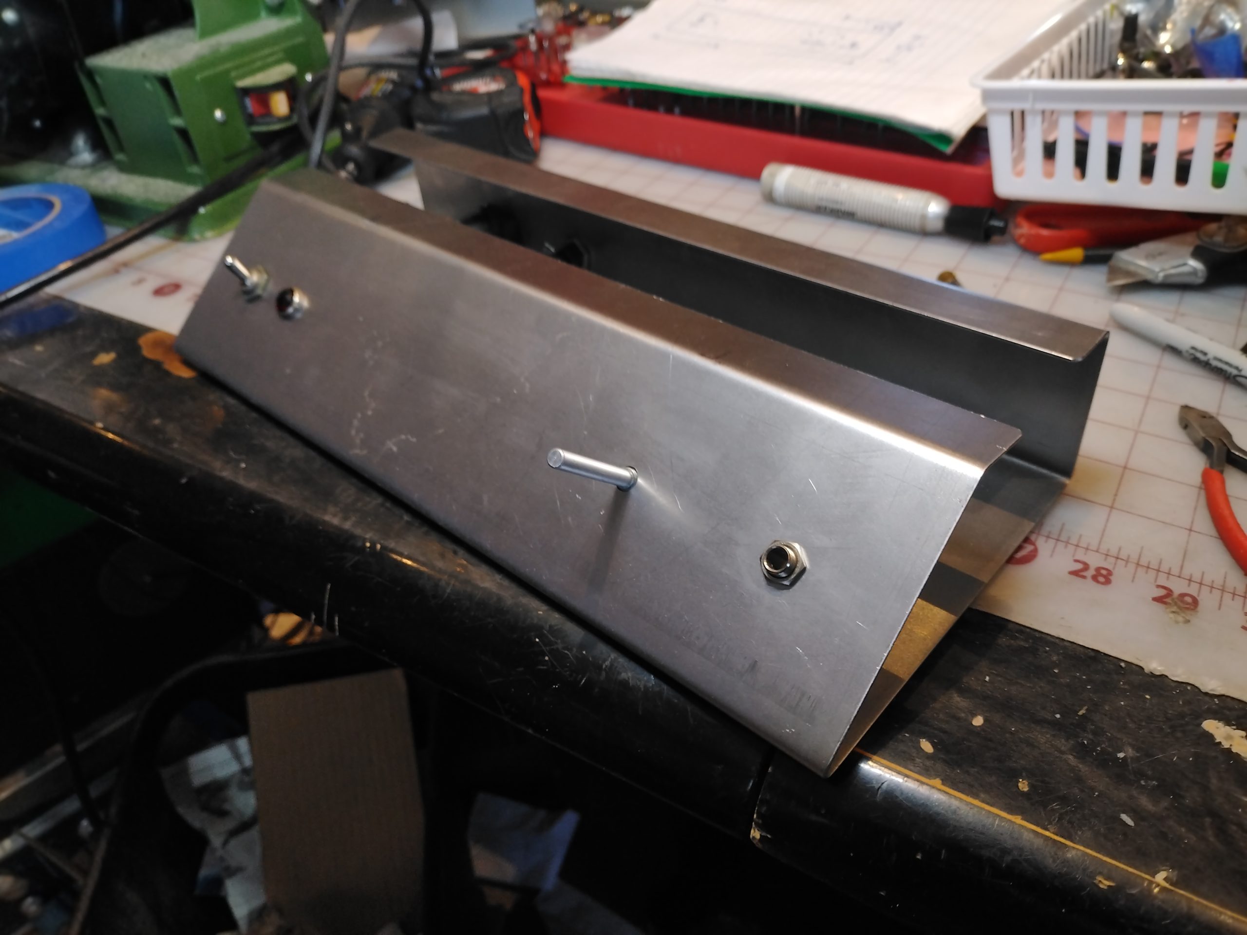
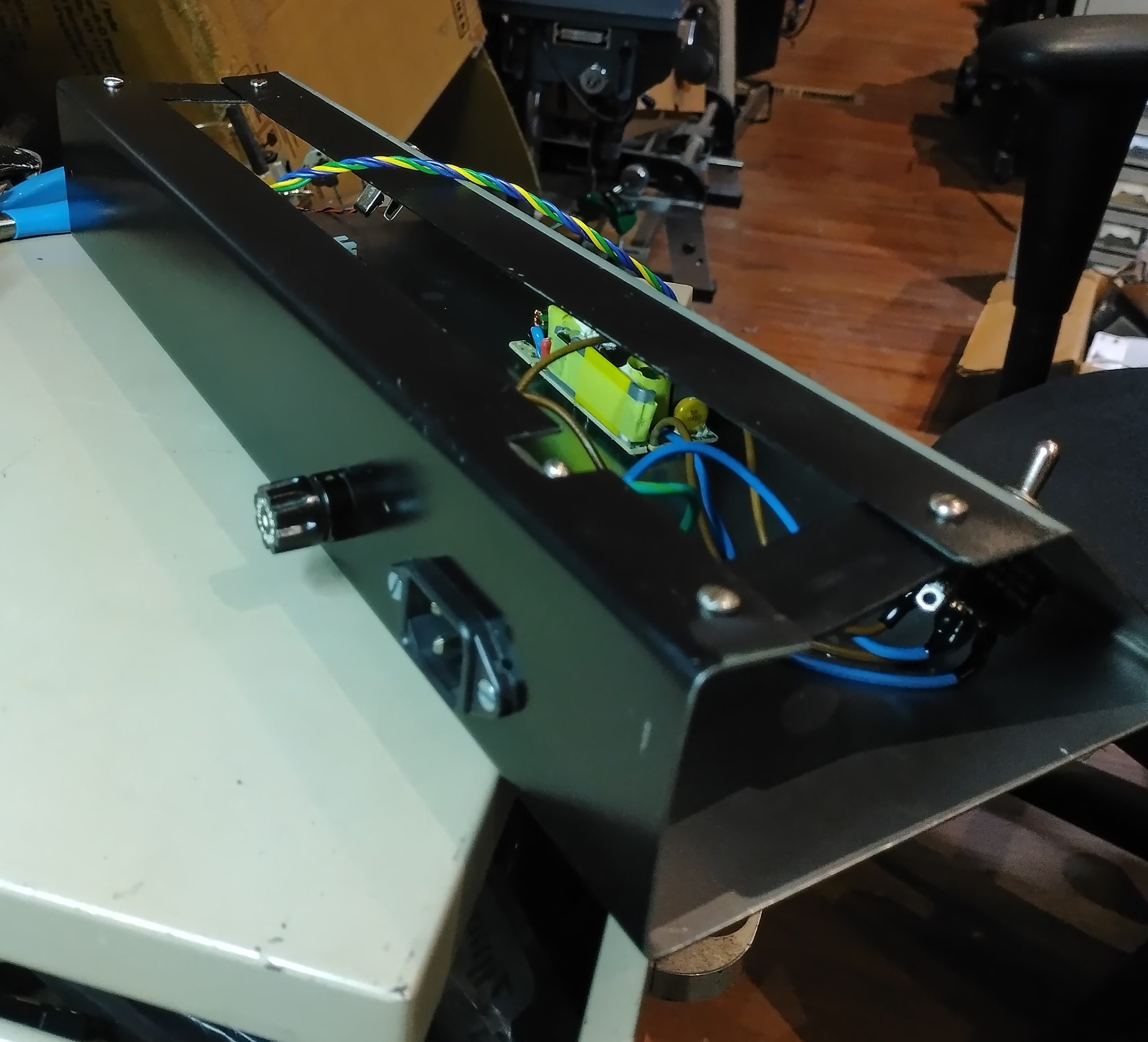
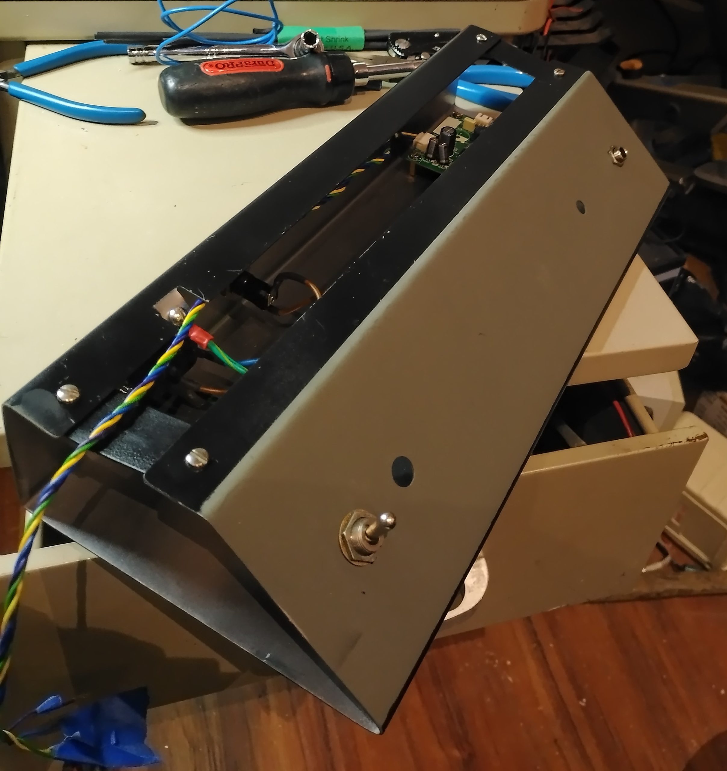
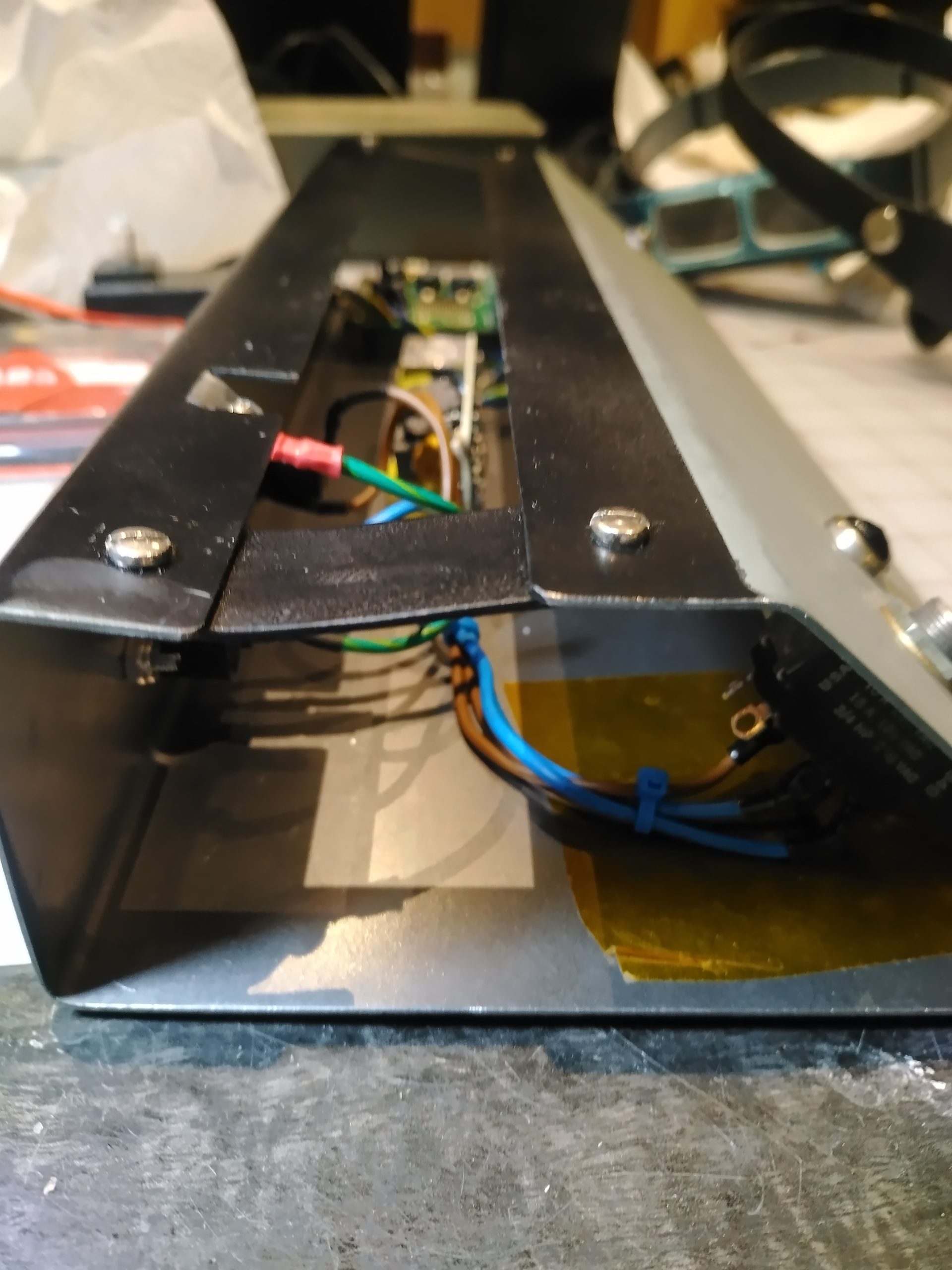
Cabinet done, on to phase three, the chassis. I wanted to go with a ’70s aesthetic with panel mounted features. No metric, all standard fasteners. An exception was the use of an IEC C14 inlet instead of a period-correct, strain-relieved, permanently attached power cord, because, gosh, they’re just so darn handy. If you need a longer power cord, just swap it out. If you need to plug it into a foreign outlet, just change out the cord and this amplifier will work fine.
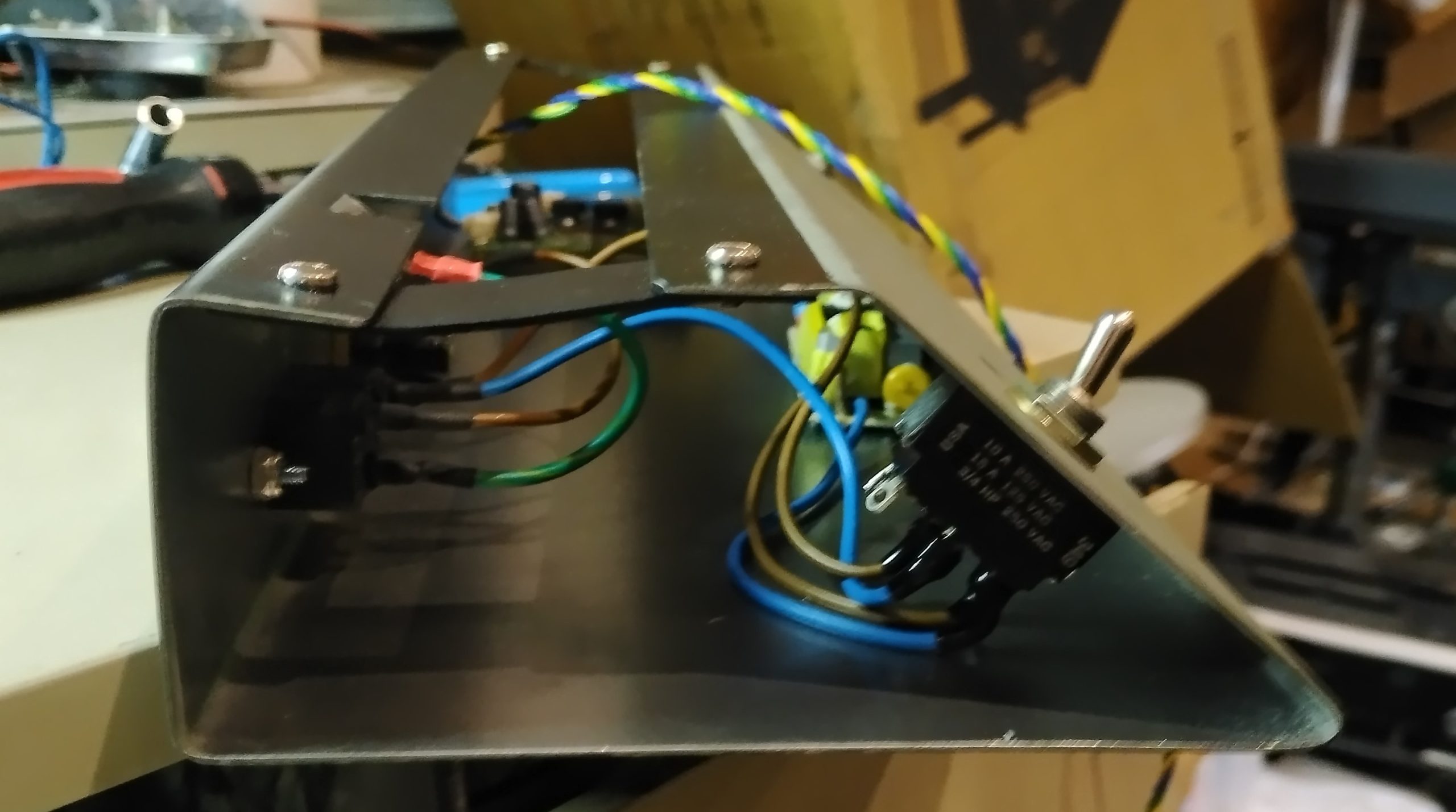
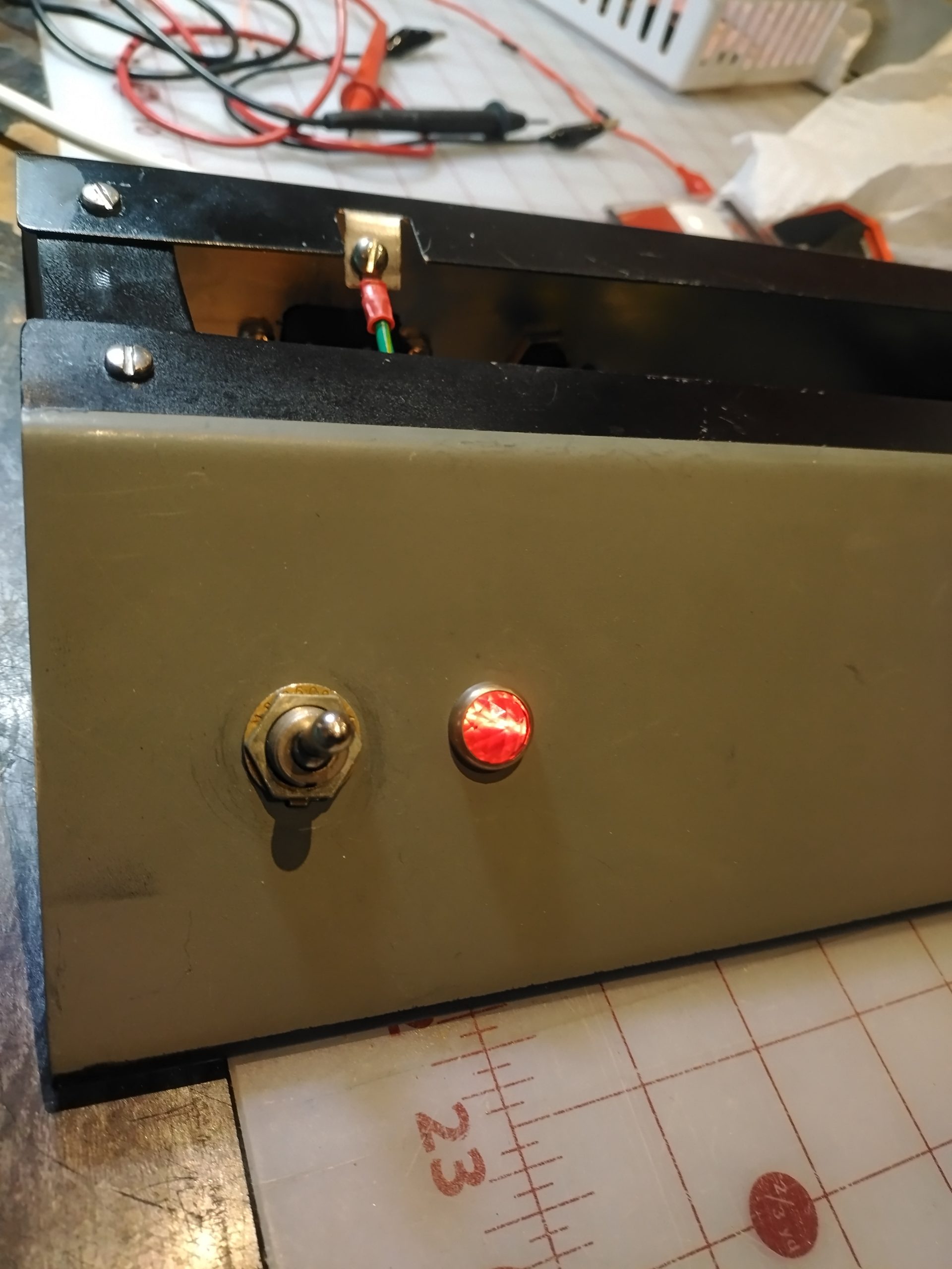
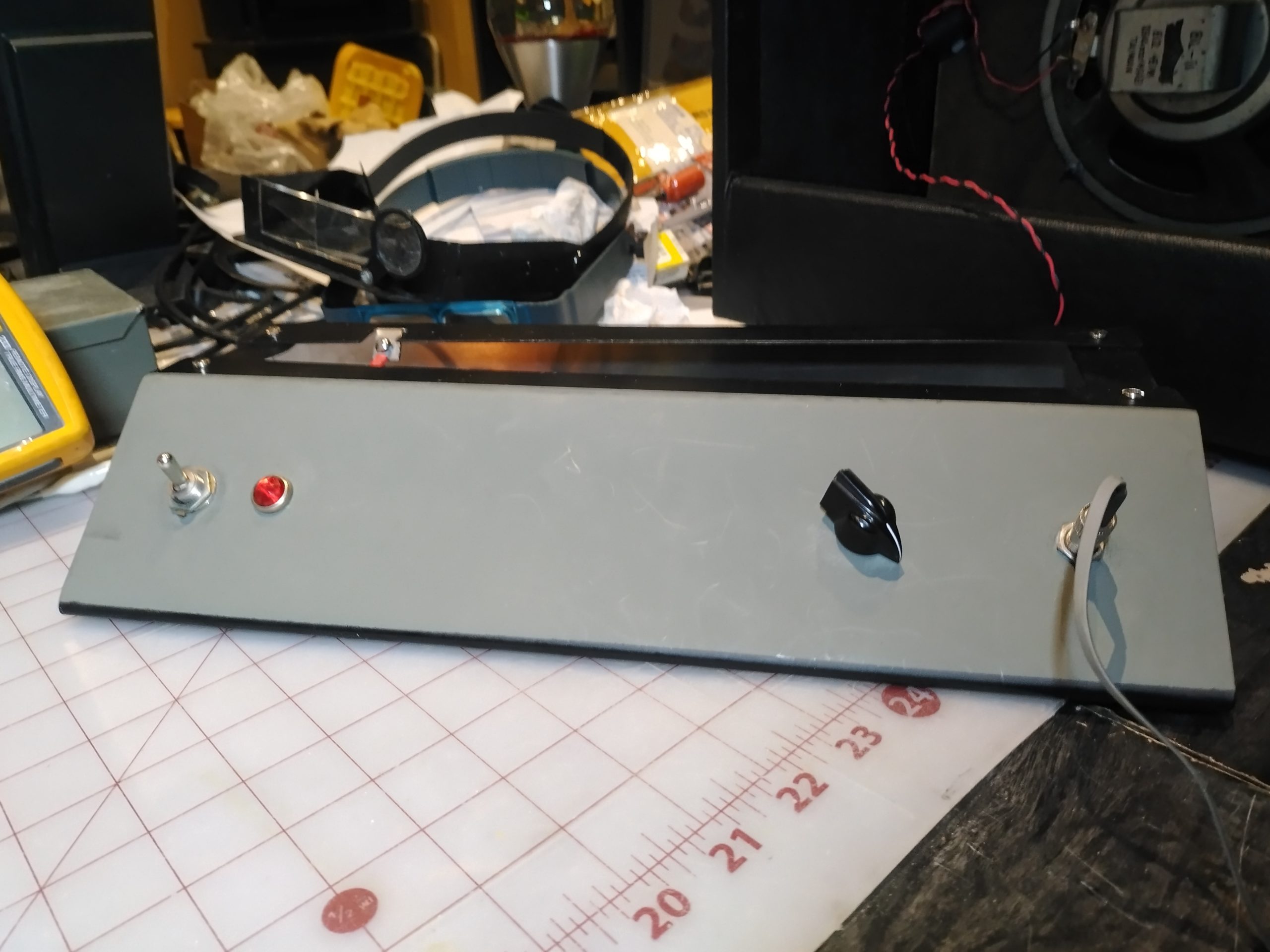
I used several vintage USA made parts: the power switch, the pilot lamp, the volume knob and the fuse holder. The knob is an actual vintage Daka-Ware product made in Chicago Illinois. The company is still in business. This one, which is probably fifty to seventy years old, was picked out, polished up, and the indicator line re-painted. The pilot lamp lens is made of real glass and is probably over seventy years old. I have several treasures like these covered in a thick layer of dust and rust in a dark corner of my basement. I picked out the lens and a lamp holder and restored both for the project.
For the pilot lamp itself, I contemplated running it on line voltage using an NE55 neon lamp. The one NE55 I could find, did not seem to work. I also thought that, considering how old the lamp holder was, it might be safer to run it from the power supply itself. I found an old U.S. made Sylvania 1829 lamp that would fit the socket and polished the decades of tarnish off of the brass base. The 1829 is rated for 28 volts, so with running it at 19 volts D.C., I feel that it should last a long time.
To turn up the difficulty factor, I chose to put the face of the control panel at an angle. This was so that the controls, indicators, and legends would be visible and accessible, whether seated or standing, and to recess them below the outline of the cabinet. Should it get tipped over or something stacked on it, the controls would not get damaged. The cabinet was laid out to match. The rear of the chassis is also recessed so that if the amplifier falls over backwards, it will not damage the IEC power inlet or the external fuse holder.
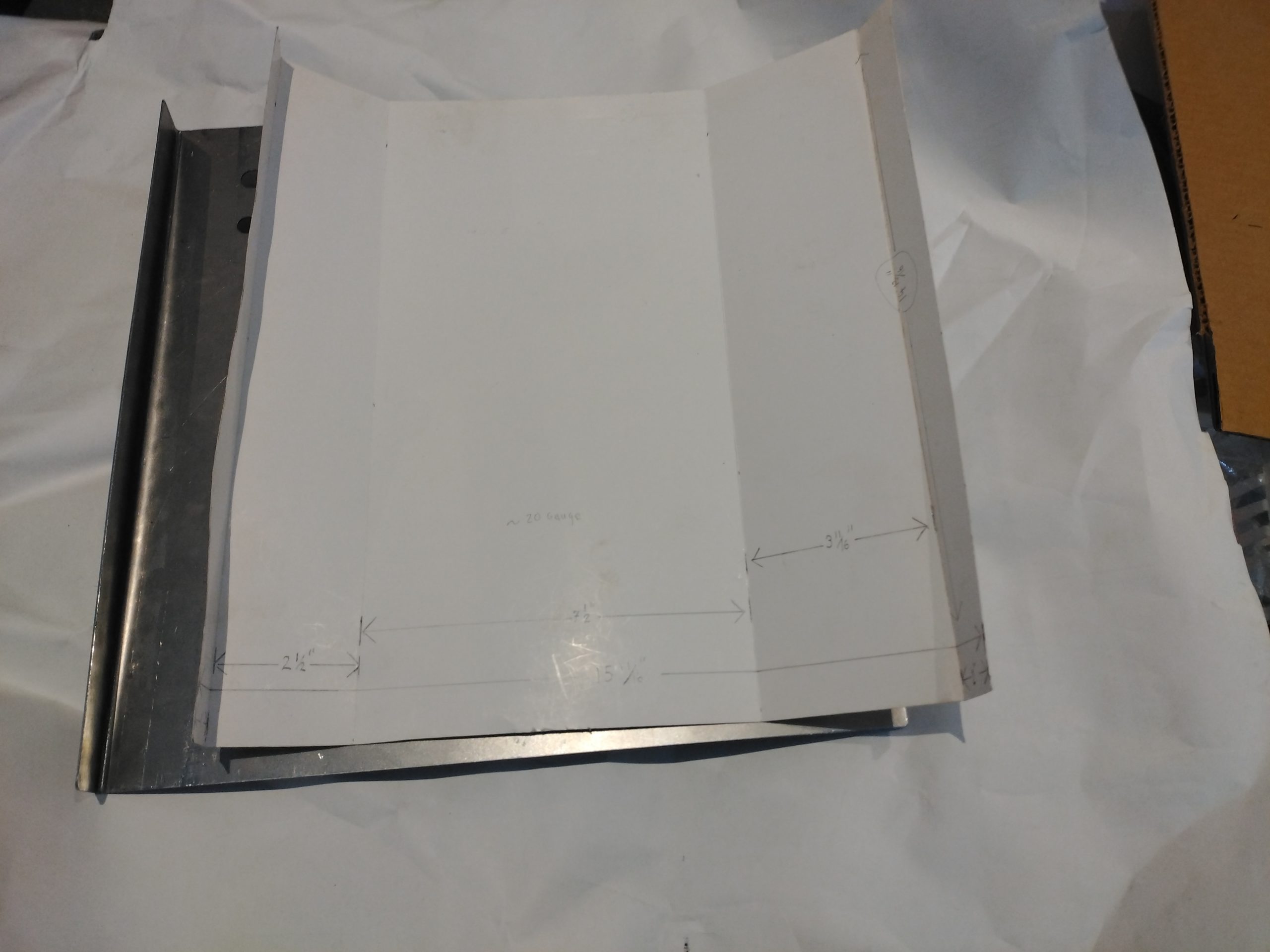
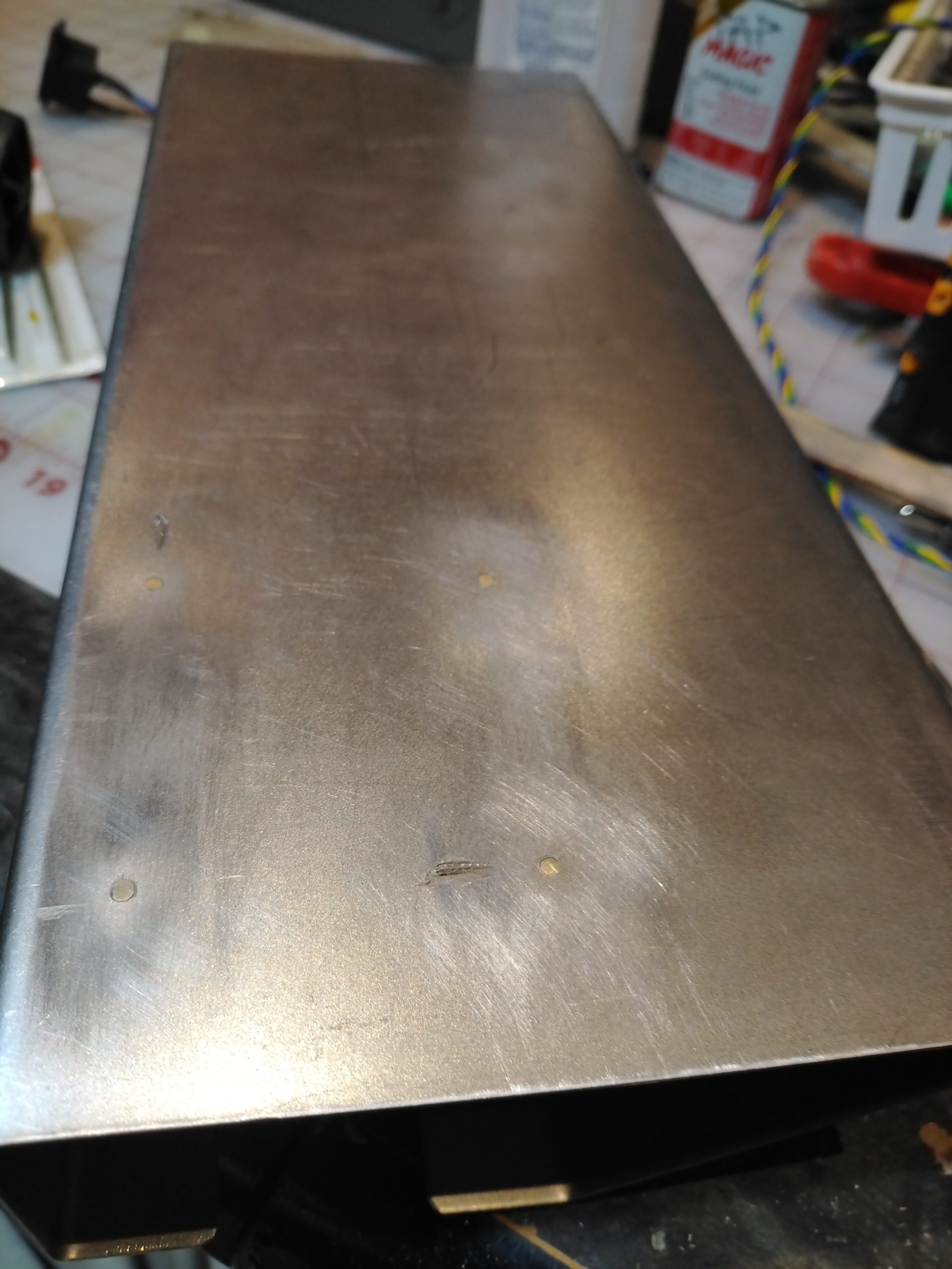
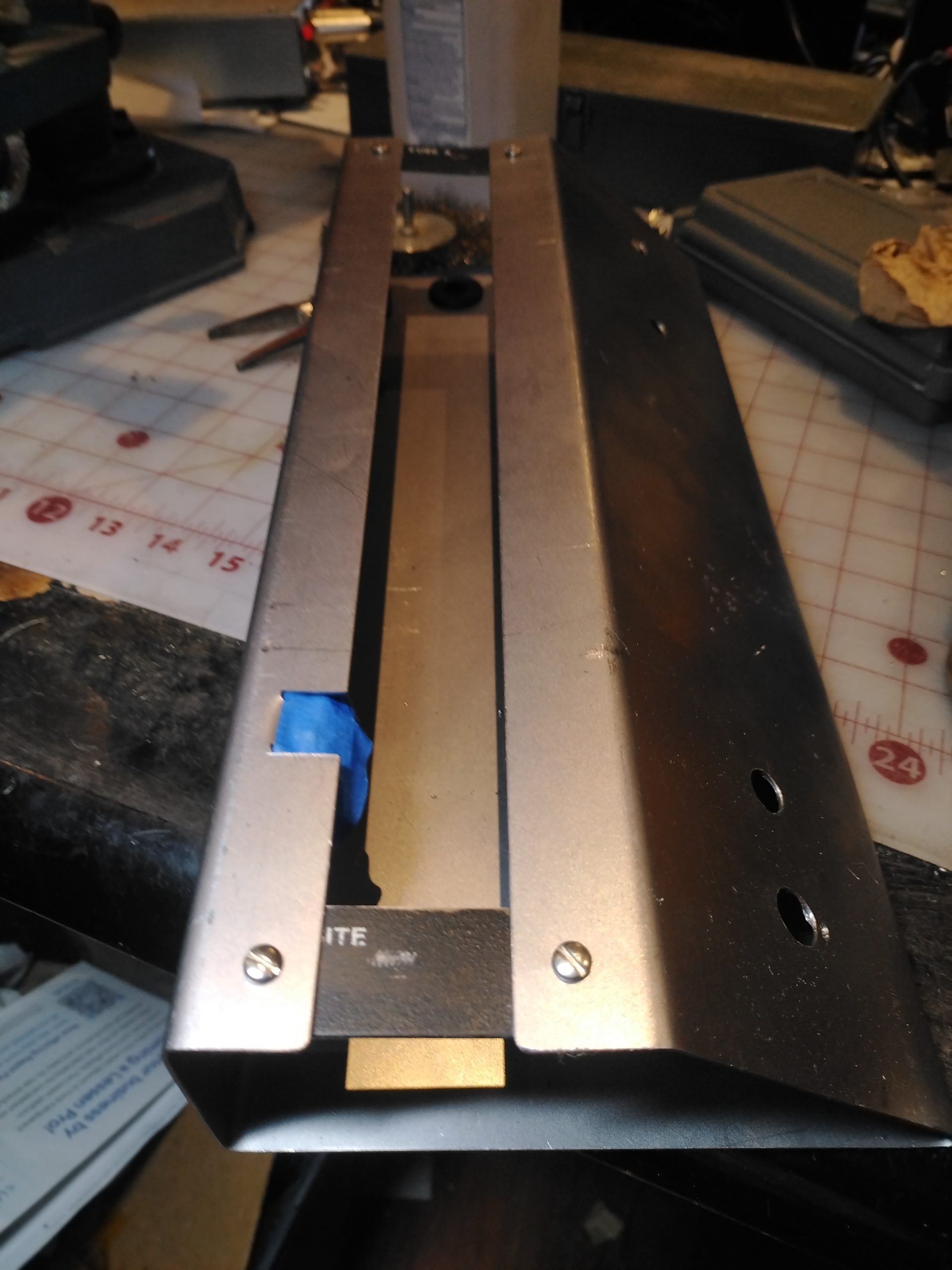
I had hoped to find a piece of sheet metal I could use, but never did. Because of the the way it is folded from a single sheet of steel, it needed to be close to 16″ x 16″. I probably could have drug home a cast-off white good to cut it out of, or pieced together smaller pieces but purchased instead. That stuff is expensive and is my biggest source of shame in this project.
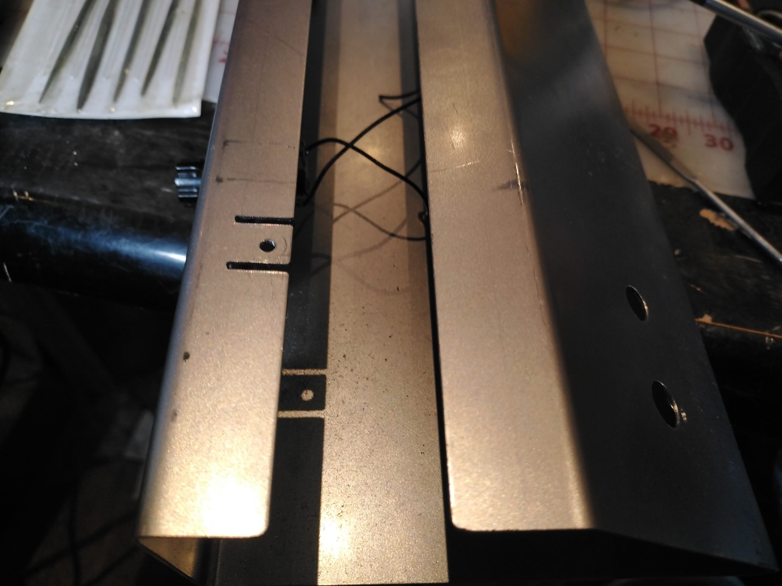
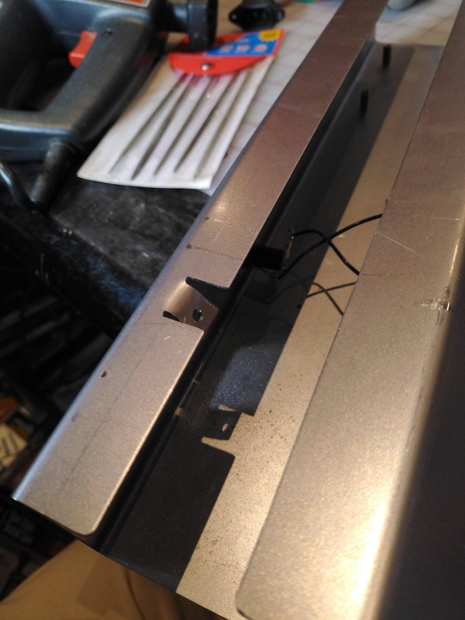
The chassis was laid out using C.A.D. (cardboard aided design), bent, and twenty-two holes of differing sizes precisely located and drilled.
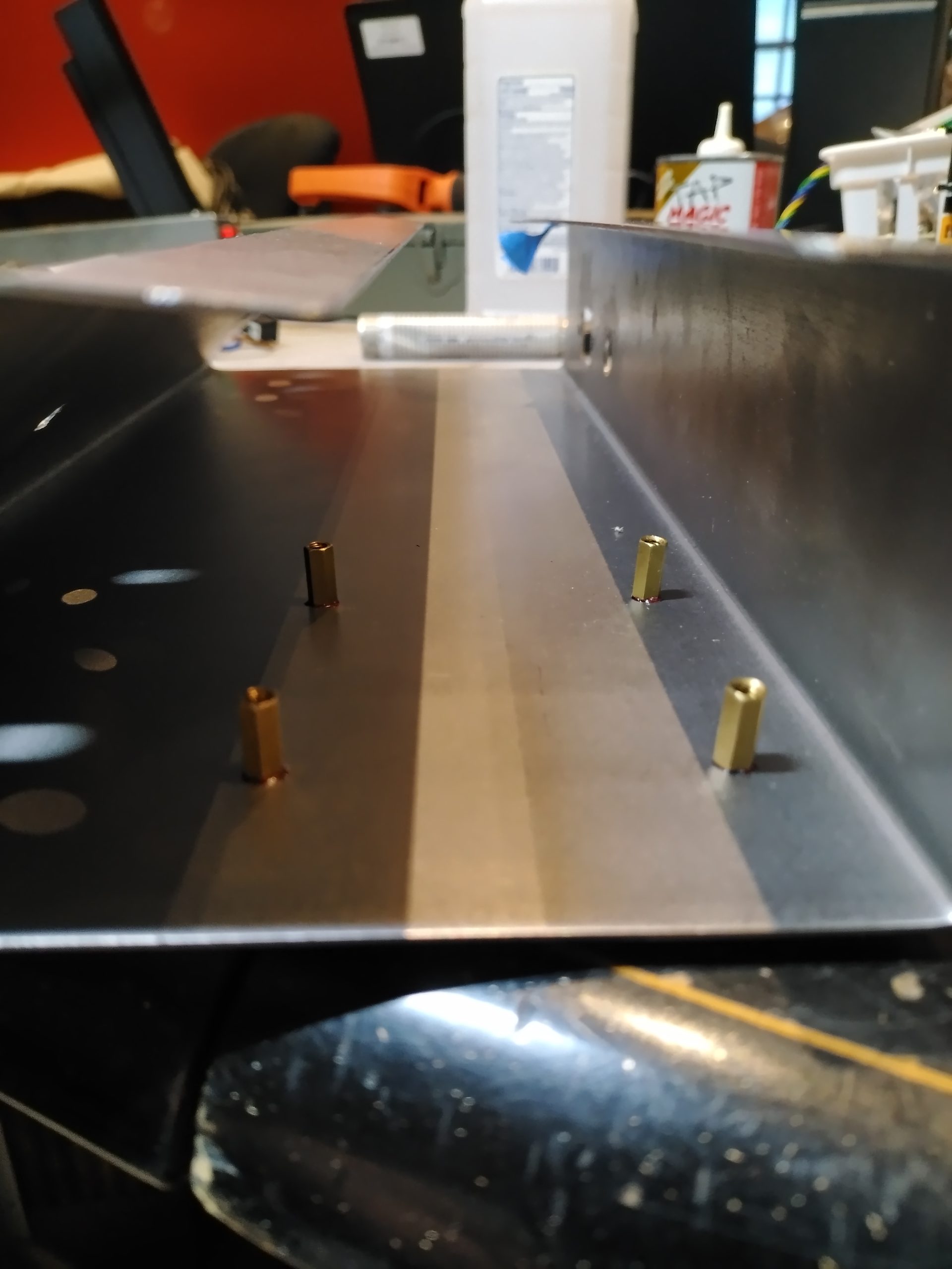
… and then cut flush.
Phase four: legends, tags and decals. This was nearly as lengthy as the cabinet build. I wanted the control panel legends painted on, a specifications/warnings decal for the rear, a QA tag, and an etched brass model and serial number tag.
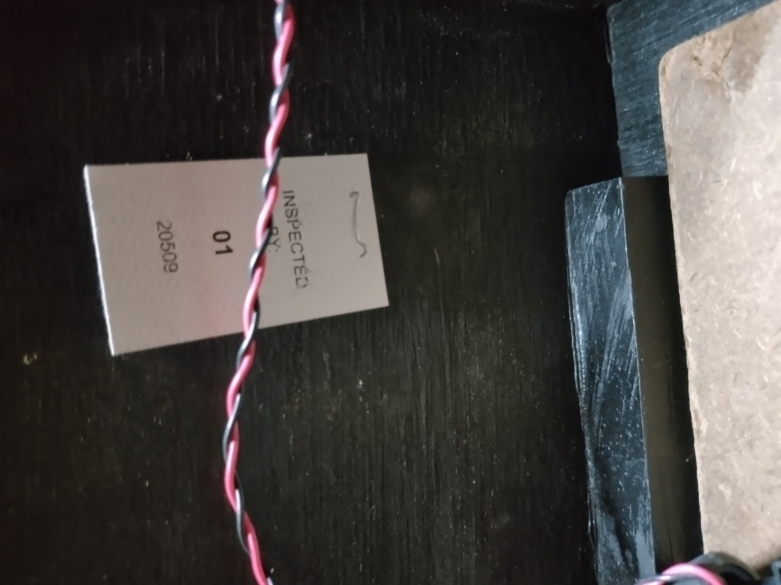
The easiest was the QA tag, although it turned out to be rage inducingly difficult. The plan was to laser print it onto card stock, cut to fit, then staple to the inside. The card stock I used was perforated post card stock for inkjet printers. Initially the toner refused to fully fuse with the paper for some reason. I abraded the paper and eventually got a good print. I then found out that I do not own a heavy-duty stapler. An office stapler will not penetrate old plywood very well. It will also not fit into the cabinet vertically when unfolded.
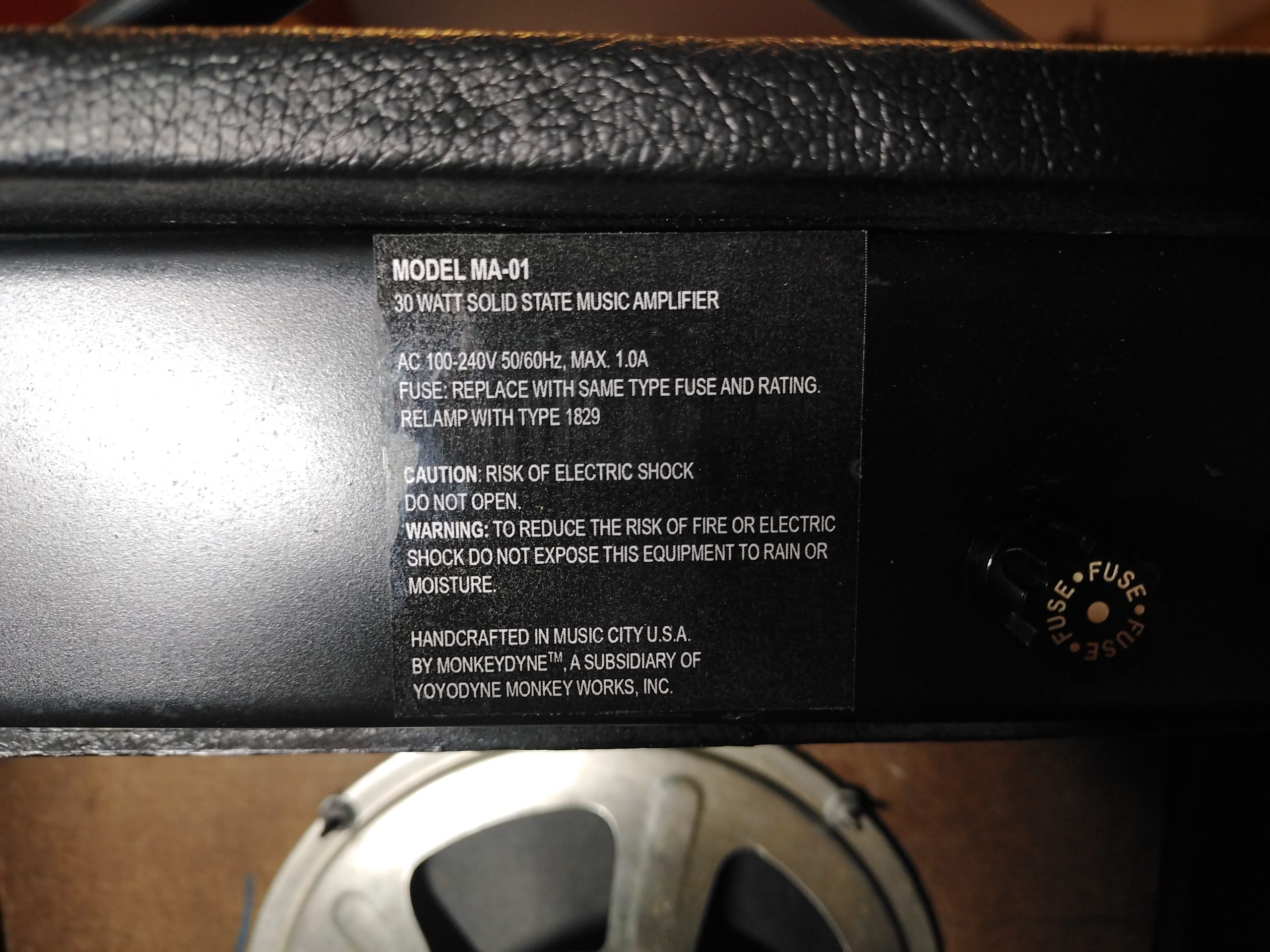
The specifications/warning decal was laser printed onto office copy paper, laminated, trimmed, and affixed with 3M 90 adhesive. The solvents trapped by the laminate caused the decal to bubble. It then had to be scraped off. I had successfully done this before with 3M 77. On the third attempt, I sealed the front and back of the paper with automotive lacquer before laminating. I then hand brushed on the 3M 90 adhesive to control the amount applied, let it dry briefly, and then stuck it on slightly crooked. The important thing is that this project is completed.
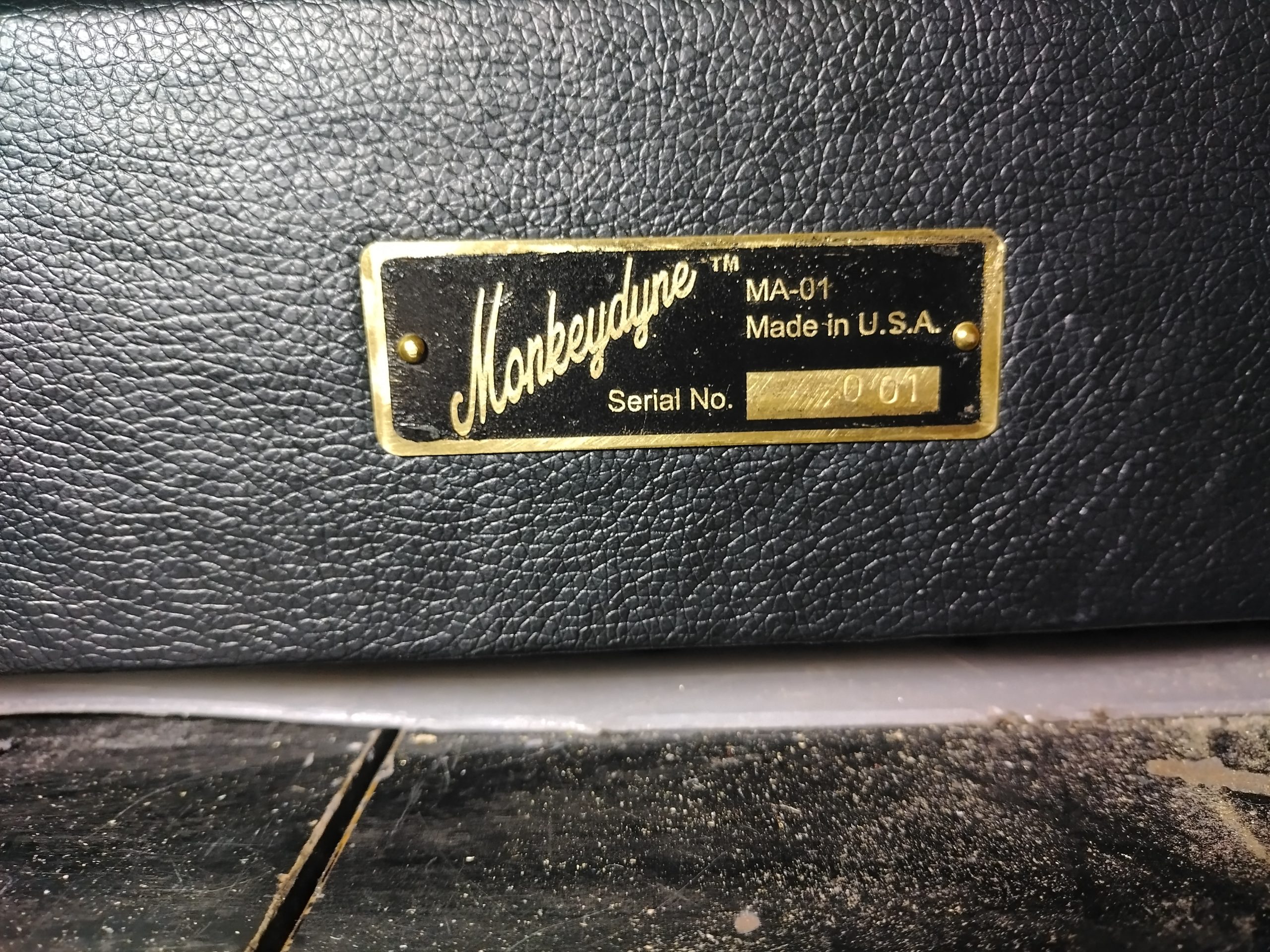
The etched brass tag was created using the toner transfer method and ferric chloride. It was then paint filled. Next it was hand stamped with number punches for the serial number and affixed with brass escutcheon pins purchased from the local Ace Hardware store. It was the first attempt and is not perfect, but the important thing is that the project is completed.
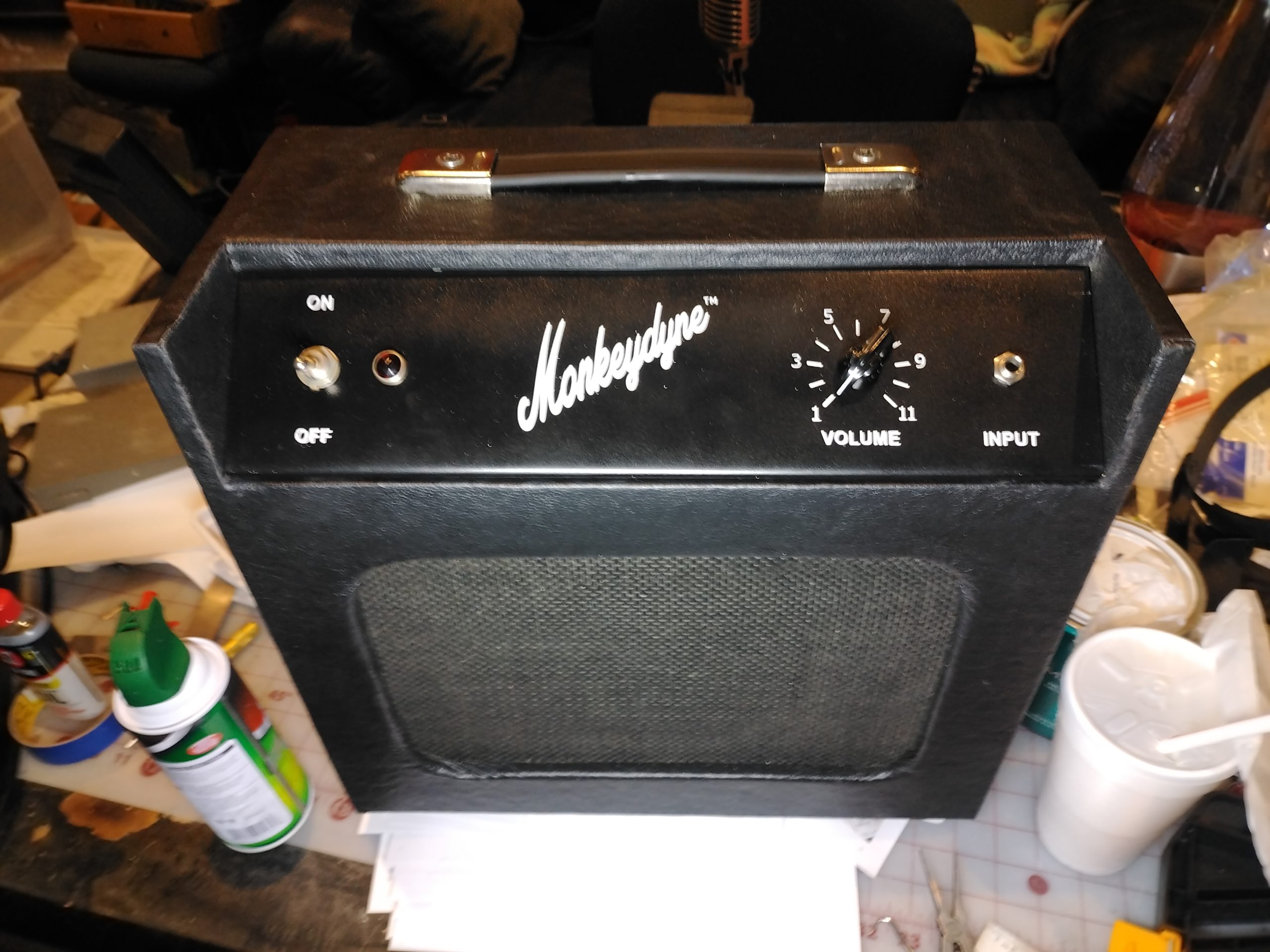
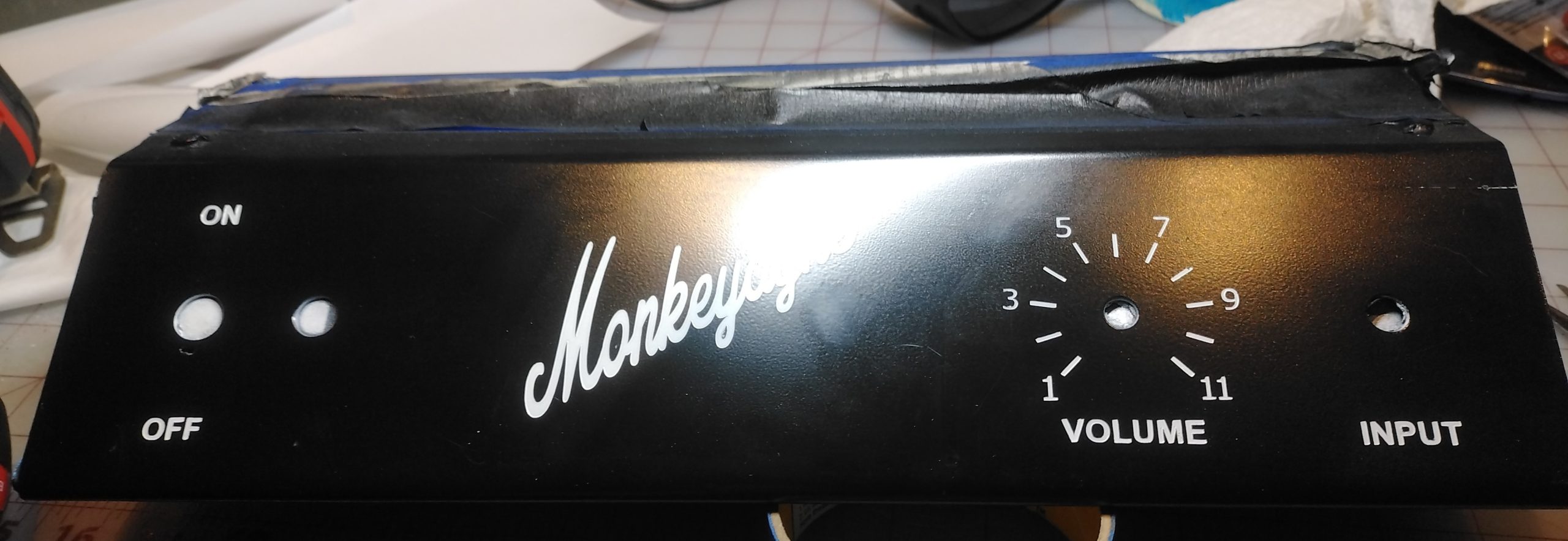
I laid out the control panel using Inkscape. I had to figure out how to distribute numbers and tick marks in an arc around the volume control. I wanted the first and last digits of the volume level to align with the start and end travel of the potentiometer. There are two popular degrees of rotation for potentiometers. I picked what I thought mine was and didn’t quite hit the mark. I also had to find the type face I wanted and how to distort it in the manner I wanted.
Painting the control panel legends took six attempts. On the first attempt, I used a laser cut stencil made from cold laminating sheet. This did not go well. The laser makes crisp corners on the paper backing to the clear vinyl, but the vinyl itself gets cut with rounded corners. Previously, I had successfully used this technique on a larger scale to paint addresses onto mailboxes. I sanded off the control panel and repainted. Even though I had sanded down to the primer, I was surprised to see an imprint of the legends showing through the paint. I sanded again and primed and painted. Future attempts were done on a practice piece.
On the practice piece, I tried using a stencil cut with a Cricut from their Smart Vinyl. This also did not go well. I then purchased Cricut stencil vinyl and tried again. This was a little better. I finally had a breakthrough when I stumbled across a comment on the Internet regarding stenciling with the Cricut. Here’s the trick: In my case, I am painting white letters onto a black background. You stick the stencil on the black ground, then paint the stencil black. This seals the stencil from paint getting under the stencil. You can’t see this seepage, because it is black on black. Then you paint the stencil white. Success!
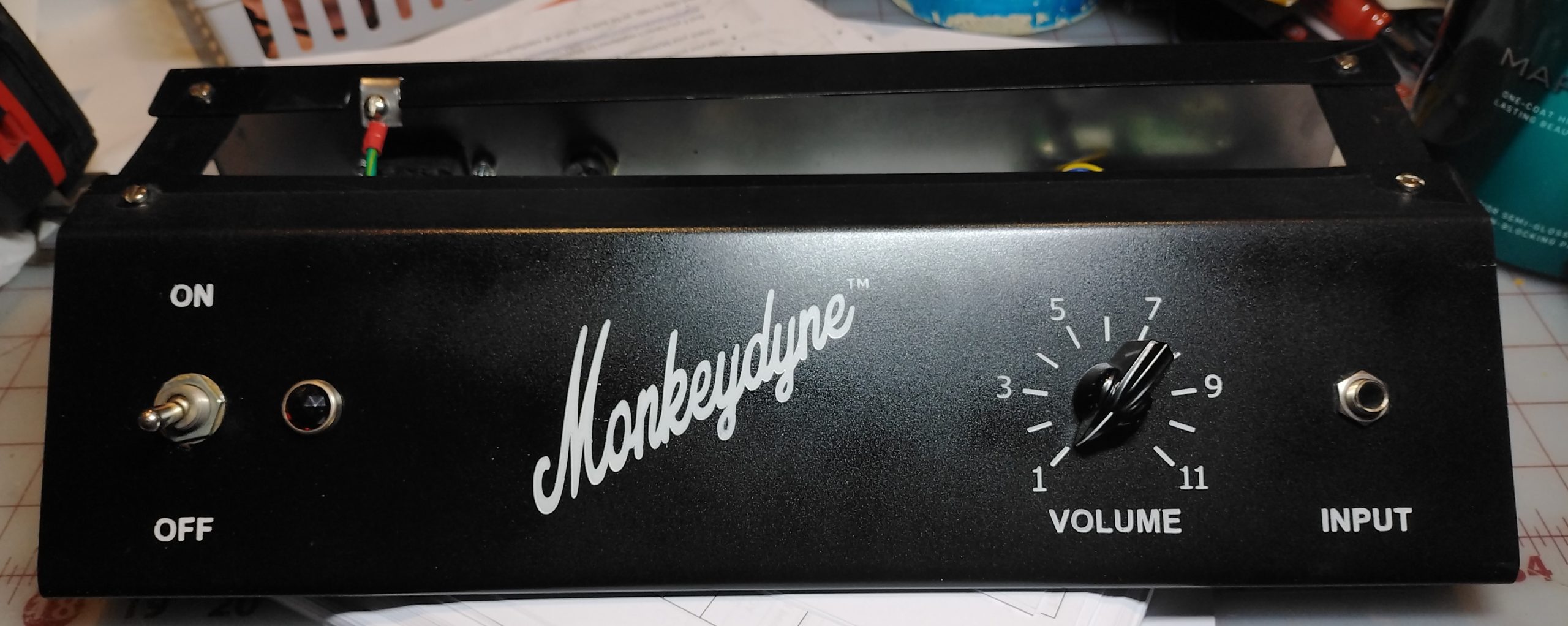
As an accessory, I made up a 1/8″ stereo phone to 1/4″ mono phone plug adapter cable by cutting the cable off an old pair of head phones and adding two 1K summing resistors and wiring them to an old 1/4″ phone plug. So now you can play a smart phone or other device through the Monkeydyne™ MA01 amplifier. I hoped you enjoyed following me through this four month journey.


Comments